CNC-Fräse

3D-Scanner - CNC-Fräse - Laser - Reflow Oven - 3DPrinter (Prusa XL, Prusa Mk3S, Prusa Mini) - Vinylplotter - Schweißinverter -Tischbohrmaschine - Drehbank - Ultraschallreiniger - Nähmaschinen
| Language: | English |
|---|
| CNC-Fräse | |

| |
| Eigentümer: | Metalab, some Parts of the machine are held private |
| Status: | Aktiv |
| Erfordert Einschulung: | Ja |
| Erfordert Authentisierung: | Nein |
| Kostet: | |
| Hilfsbereite: | CNC Mailing List |
WARNING: Do not use this machine if you have not had an official introduction to the workflow of this specific machine. It is quite complex and working with this device can easily result in a visit to the hospital...
CNC aka the Geil-o-Mat
What is it? It is a CNC (Computerized Numeric Control) Machine, which is located in the Heavy Machinery Department of the Metalab.
Technical Outline:
- Spindle speed: 6000 - 24000 min^-1
- Tool Size: 1mm up to 8mm shank, also 1/8" shanks
- Maximum step speed: 2000 mm*min^-1 (3600mm*min^-1 for G0, z-axis max 1200mm*min^-1)
- Maximum Workspace Dimension: about 725mm * 395mm (X*Y). The height depends on your workpiece, millhead and where do you fix it!
- Maximum Workpiece Dimension: about 510mm in width, the length is up to a few meters when the cage is opened. The T-slot plate is ~104.9x48cm.
- Cooling: Air (or liquids by hand)
- Clamping: Various - depends on your job
- Software: Runs via LinuxCNC (an Open Source CNC Software)
- Materials: wood, PCBs, plastics, (millable) aluminium (with precaution!); NO steel (never ever)!
For projects results of this machine, please visit http://geilomat.soup.io/
Ask on our Mailinglist for help: https://lists.metalab.at/mailman/listinfo/cnc
Take also a peek into the LinuxCNC Wiki! There are really good articles about CNC Stuff too!
Standard Procedure
Before you can start milling
Using the CNC is not as straight forward as using the Lazzzor. From the handling, it can be compared with a 3D-Printer but there are still more steps involved.
To work with the CNC machine you need the following things ready:
- G-Code
- Cutters suiteable for your material
- Material
- A method to fixate the material in the machine
- A method to measure workpiece coordinates and save them in LinuxCNC
While the Material and Cutters are usually not the biggest problem (see CNC and Benutzer:Fbr/WhereToGet for more information), G-Code generation is probably the hardest part. Also fixating the material can be challaging, as well as measuring the workpiece coordinates.
The easiest way to get G-Code is using CAM software. Such a software can "convert" CAD parts into G-Code. There are some OpenSource projects but most of them are not really powerful and only work for simple pieces. See also CNC#CAM for a list of Tools. Expensive CAD software has also powerful CAM modules, but they are in the range of 10k€ or more.
Fiaxting plates and rectangular workpieces isn't a problem, as we have a set of clamping claws and a T-slot table. For other pieces it might be a good idea to build a fixature first.
Measuring the workpiece isn't too hard either, if working with non-complex geometries.
Ask for help, if you need to clamp or measure an complex part! There is always some trick you can use.
Here is a good example for the workflow of CNC machining (and some more explanations) using Autodesk Fusion and Mach3/4 (quite similar to LinuxCNC): CNC Dummies For Routers & CNC Basics 2
Start Up

There are some important steps to take, otherwise you can destroy everything - even the earth... If you don't switch on the things in this particular order it can happen that the machine does things out of nowhere e.g. moves or turns on the spindle!!!
- Start CNC PC (do not turn on the G4 (The "G4 Case" stepper control thing), neither the VFD)
- Start LinuxCNC, make sure the X-Box controller is plugged in, otherwise starting the LinuxCNC doesn't work
- If you are using the T-notch plate, choose the Shortcut "Geil-O-Mat starten (T-Nut Platten, Z Limit 107mm)"
- Otherwise choose "Geil-O-Mat starten (Z Limit 112.5mm)" which has extra 5.5mm Z-Axis travelling distance
- Press the emergency stop at the machine frame (if not already pressed)
- Power on the Stepper Driver (The G4 Case)
- Plug in the Variable Frequency Drive (VFD)
- Wait until the VFD is started up
- Check if 100.0 Hz is set on the screen of the VFD
- Otherwise rotate the rotary encoder that it is 100.0Hz
- Now release emergency stop
- Power on the Machine inside LinuxCNC
- Move near Homing position
- Start Homing Sequence ("Referenzfahrt")
- Warm up the Spindle as described here in the wiki
Now the machine is ready to use.
For milling the spindle needs to be warm. The manual says that you should first let the spindle run for about 1 minute on 6000rpm, then increment by 6000rpm for 1 minute until you reached your destination speed. If the spindle wasn't used for longer than one week, you should double that time. So better is to let it run for two minutes on each speed.
There is a sample code in the GCode Section
Power Down
- Move Machine in a position where you can easily clean it and remove millheads. The back right corner is a good choice!
- Press Emergency Stop
- Plug out VFD
- Shut down Stepper Drivers
- Exit LinuxCNC
- Power off PC
- After seeing "System Halted" press the Power Button of the PC
- Remove Cutter and Clamp
- Clean the machine-bed and everything else.
Machines and Things around the CNC
- CNC PC: a Linux machine running the LinuxCNC Software and sends out commands via Parallel Port
- G4: a old Apple G4 Case holding the stepper drivers and breakout board
- Stepper Driver: Each stepper driver controls one stepper. There are 5 Stepper Driver in the G4: 2x X, 1x Y, 1x Z, 1x A (currently unused)
- Breakout Board: Is used to "convert" the parallel commands to a different protocol that the stepper drivers are using. It controls also the spindle speed by sending an appropriate signal to the VFD
- VFD (Variable Frequency Drive): This Box controls the Spindle. It has a output of 100 to 400Hz on 3 Phases and gets controlled by the Breakout Board.
-
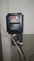 VFD, controls the spindle speed
 -
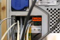 Stepper Driver Power Switch
 -
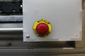 Emergency Switch
 -
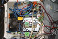
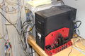 CNC PC (in the front) and "G4" Stepper Driver (back)
 -
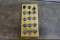 Our set of collets for the Spindle
 -
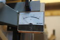 Power Consumption Meter at the output of the VFD
 -
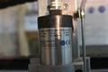 The Spindle
 -
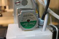 A Stepper Motor
 -
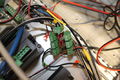
 The Stepper Drivers inside the "G4"
 -
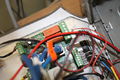 The Breakout Board converts parallel port to stepper drivers and VFD
 -
 You can add more emergency switches to this board
 -
 The Homing switches are used to give the machine a home position
 -
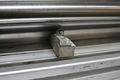
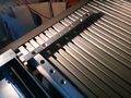 Aluminium profiles are used as a side lay, for easy and repeatable positioning of the workpiece


Wie Spanne ich ein Werkzeug richtig ein
Wahl der richtigen Spannzange
Der Spannzangensatz ist zwischen 1mm und 7mm auf 0.5mm gestuft. Stimmt der Nenndurchmesser des Schafts mit dem Nenndurchmesser ein Zange überein, dann nimmt man die. Für Zwischenwerte die nächst größere Spannzange. Für 1/8-Zoll-Schäfte sind eigene Zangen vorhanden, für 1/4-Zoll leider nur die 6,5er-Zange Der kleinste Schaft, den ich mich in die 1mm-Zange spannen traue ist 0.7mm
Überwurfmutter
Wie auch bei der Kress-Spannzange ist als erstes die Spannzange in die Spindelmutter (Überwurfmutter) einzurasten. Die Zange sitzt richtig, wenn ihr Aussenende (nahezu) plan zur Mutter ist (auch nach dem Aufschrauben auf die Spindel prüfen, bevor man fest anzieht). (Bei genauer Betrachtung der Mutter fällt auf, dass der Bund, der in den Einstich der Spannzange einrastet exzentrisch zur Achse der Mutter ist. Das ist Absicht und erleichtert das Einrasten.)
Einbau des Werkzeuges
Das Werkzeug in die Spannzange (in der Mutter) einstecken Manche Fräser haben eine Flachstelle am Schaft. Die Enden der Spannzange sollten nicht in diesem Loch zu liegen kommen, da sonst die Zange asymmetrisch spannt und eventuell beschädigt wird. (Das innere Ende Spannfläche muss nicht das Ende des gesamten Körpers sein, manche Zangen sind abgesetzt) Bis 7mm ist es möglich, den Werkzeugschaft durch die Zange in die Spindel zu stecken. Bei der 8er-Zange geht das nicht!
Montage des Werkzeuges
Die Zange mit dem Werkzeug in die Spindel einsetzen und Mutter aufschrauben Da die Zange im offenen Zustand, speziell bei Bohrern, die etwas kleineren Schaftdurchmesser haben, das Werkzeug nicht halten kann, folgen die Werkzeuge gern der Schwerkraft. Man braucht einen 13er-Schlüssel für die Spindelachse, einen 17er für die Mutter und eine 3. Hand, um das Schneidwerkzeug zu halten. Oder doch nicht? Wenn man die Y-Achse und Z-Achse geschickt positioniert, kann man den 13er auf die Schleppkette auflegen und gegen das Portal lehnen. Alternativ kann man einen Holzblock unter das Werkzeug stellen. Es schadet generell nicht, bei offenem Arbeitsraum-Boden (so wie jetzt wo ich oft werkel) eine Holzplatte unter der Spindel am Boden aufzulegen, falls das Werkzeug doch "abpascht" (beim Ausspannen!).
die Mutter anziehen
Wie oben erwähnt jetzt noch mal den richtigen Sitz der Zange prüfen! Das Gewinde der Mechatron-Spindel ist sehr fein, daher erzeugt es schon bei mäßigem Drehmoment recht hohe Axialkräfte, die letztendlich die Zange schließen. Das erzeugt Radialkräft auf den Werkzeugschaft, die über Reibung das Werkzeug halten. Wie wir alle wissen, ist die Flächenpressung, die ein Werkstoff erträgt begrenzt und gleich Kraft durch Fläche. Die Pressfläche ist bei kleinen Zangen viel kleiner als bei großen, daher speziell diese mit Gefühl anziehen. Wenn alle Spiele aus der Anordnung verschwunden sind, gibt es einen Punkt, wo das Anziehen "hart" wird. Über diesen Punkt hinaus sollte man nicht gehen.
Aus- und Einbau der T-Nut Platten
Sollte jemand die T-Nutplatten aus arbeitstechnischen Gründen entfernen müssen, dann bitte folgendes beachten:
a) hinter der hintersten T-Nutplatte sind auf dem Rahmen links und rechts jeweils ein Nutenstein mit Wurmschraube und einer Zylinderkopfschraube fix montiert. Beim Wiedereinbau die erste T-Nutplatten vorsichtig an diese Köpfe anschieben. die folgenden beinde jeweils spaltfrei anschschließen. Bitte die Platten nicht verdrehen. Aktuell ist auf der linken Seite duch die Bohrungsmittelpunkte ein schwarzer Strich gehend.
b) Damit die T-Nutplatten lange leben und eine glatte Oberfläche behalten, bitte bei Durchfräsungen bzw. Durchbohrungen durch Euer Werkstück eine entsprechende Opferplatte dawischen einspannen. Falls jemand nicht genau wissen sollte, was damit gemeint ist bzw. wie so etwas eingespannt werden soll, bitte unbedingt vorher auf der CNC-Mailingliste nachfragen.
c) sollte als Opferplatte irgendein dickeres Material (MDF, Kunststoff etc.) verwendet werden um sein Werstück mit Spax-Schrauben niederzuspannen, dann bitte die Schraubenlänge so wählen, daß die Schraube die T-Nutplatte NICHT erreicht !!! Daher bitte lieber vorher 10 Sekunden nachdenken, sonst erreicht Euch die Strafe der Werkstättengeister.
- mutwilliges Hirnabschalten ---> Ersatz für Schaden (Material + Zeitaufwand) + 1 Jahr HM + WEL wöchentlich aufräumen
- nicht mutwilliges Hirnabschalten --> Ersatz für Schaden (Material + Zeitaufwand) und 1 Jahr HM wöchentlich aufräumen
GCode
See also this Page for more GCodes: CNC/GCode
Example Gcode Header for Geilomat:
; A secicolon starts a comment
(Lines inside brackets are comments too)
G21      ; use mm
G90      ; absolute coordinates
G92.1    ; cancel offset coordinate system and set values to zero
G54      ; use G54 coordinate system
G40      ; turn radius compensation off
G17      ; choose x,y plane
G80      ; Cancel Motion Modes (e.g. active canned cycles)
G94      ; movement speed is in units per minute (hence mm/min)
G49      ; turn cutter legth compensation off
; It is always a good idea to go to a known safe location to run the warmup
G0 Z10   ; Go to saftyplane, usually you define the highest part of your workpiece as Z=0
; Spindle Warmup Sequence
M3       ; turn on spindle
S6000    ; 6000 min-1 spindle speed
G4 P120  ; wait 2 minutes until spindle is warm
S12000   ; add another 6000min-1
G4 P120  ; again two minute wait
; repeat steps above (S and G4) until target speed is reached

F500     ; 500mm/minutes movement speed

; your program starts here... now you can do things like
G0 X0 Y0 ; go to your 0,0 point rapidly
G4 P0    ; Dwell for no time, to force linuxcnc to be on this point exactly
G1 Z0    ; go to Z0 with 500mm/min (as set with F command)

; the tail
G0 Z10   ; retract from workplane - safty plane
M30      ; end program
Parameters for typical jobs

Please note that these Values are produced under different circumstances - like how many "Schneiden" a mill has or what kind of mill you are using! Please use also "Drehzahlrechner" for looking up proper values.
Please be aware that, like with the lasercutter, not every material can be cut and for each material you have certain parameters. These parameters are in the first place a result of the tool you use but also depends on chemical and mechanical compound of the material you need to cut. For example there are a lot of aluminium types, like AlMgSiPb or AlCuBiPb which is very good for milling and also pure Al99,5 which is very very bad for milling!!! This counts for all types of material, also for wood! e.g. MDF has very different cutting parameters than birch wood...
| Material | Head Diameter mm | Cutting Depth mm (a_p) | Sidewards depth in % of diameter (a_e) | Spindle Speed | Feed Rate mm/min | Comment |
|---|---|---|---|---|---|---|
| MDF | 6mm Z2 | 3 | 100% | 18000 | Feed 2000, Plunge 300 | Absaugen! Das Zeug ist ziemlich fein und nicht gut für die Lunge... --Reox (Diskussion) 11:46, 9. Jan. 2016 (CET) |
| Wood | 3 | 5 | 50% | 12000-14000 | >300 | guessed proposal |
| Wood | 0.8 | 4 | 100% | 12000-14000 | ~250 | guessed proposal |
| Wood | 3 | 0.8 | 50% | 12000 | 600 | looked good, material was plywood 8mm |
| Wood (Leimholz Fichte) | 6mmZ3 | 2 | 100% | 23000 | 1000 | Works fine, also tested 0.5, 1.0 and 1.5mm |
| Wood (Leimholz Fichte) | 6mmZ3 | 6 | 1mm | 23000 | 1000 | Für Kanten, Stege auf der Holzplatte brechen aus (Achtung) |
| Aluminium | 6 | 0.25 | 6mm | 10000 | 1100 | Vierschneider, schleppender Schnitt - no external cooling |
| Aluminium | 6 | 0.25 | 6mm | 10000 | 650 | Zweischneider, schleppend und ziehender schnitt - no external cooling |
| Aluminium | 4 | 0.25 | 6mm | 14000 | 850 | Dreischneider, Wassergekühlt, leicht raue Oberfläche |
| Brass (Messing) | 2 | 0.25 | 50% | 24000 | 960 | Zweischneider - no external cooling |
| PCB engrave | 0.1-0.3 30deg | 0.3 | 0.035 | 12000 | 1000 | tested in epoxy-pcb |
| PCB drill | 0.9 | -2.5 | 0.5 | 14000 | 400 | tested in epoxy-pcb |
| PCB milling | 0.5 | 0.035 (isolate) 0.25 (mill) | 100% | 22000 | 400 | tested in FR4 |
| Plexiglass Front door engrave | 0.1 30deg? | 1 | 10000 | 20 | Plunge 20, toolsize cambam 0.3 | |
| Plexiglass egg | 1.5 30deg? | 0.5 | 14000 | 100 | Plunge 30, toolsize cambam 1.5 : 4mm thick plexiglass 400x300 | |
| Plexiglas Portrait | 0.1 30deg? | 4 | 10000 | ? | 0.3mm raster, Custom tool to convert from image to gcode | |
| Acryl | 6 | 0.5 | 5mm | 6240 | 1400 | Zweischneider, no external cooling - there are two types of Acryl: XT and GS. Use GS for Milling! Soapy water should be fine for cooling. Others report "Hirschtalg" works even better. |
Warning
Do not use a too low feed-rate!! The cutting region of the milling head is microscopically round. If the "Spanbreite", the thickness of the removed material, is lower that this radius, most material is compressed and only cut if the compression force is to large. This results in dramatic friction and hence only heats up the milling head. The thought "Oh, the cutter is getting too hot, I can see burning marks in the side of the wood, I have to reduce the movement speed" is deadly!!! You can decrease the spindle speed, and increase the movement speed.
The Heat produced while cutting depends on the friction. A second part is proportional to the volume of material that is removed. Half the milling depth, half the heating! 25% sidewards instead of 50% sidewards cutting=half the heating.
Mill heads can break if the sidewards force is too large. So for tiny things, the feed rate together with the spindle speed and the cutting depth should be reduced.
Pocketing plexiglass
- Choose engraving bit according to pocket size.
- Be careful with CutIncrement (1mm is ok).
- Be aware that plexiglass melts, so it's important to use cooling.
- For bigger pocket operations, the vacuum cleaner has a certain cooling effect.
- Air pressure and water cooling was necessary for the front door window engraving.
Cutting GFK (glasfaserverstärkter Kunststoff)
(Acquirable at http://www.der-schweighofer.at/artikel/77271/gfk_platte_300x135x1.5mm)
The following values work fine for cutting 1,5mm thick GFK.
- Plunge Feed-rate: 100
- Cut Feed-rate: 1500
- Depth Increment: 0,8mm
- Feed override: 75%
Aluminium
- tldr
- Cutter diameter should be around 4mm to maximum 6mm on our Machine.
- cutting speed and feed rate per tooth are the important parameters
- Better not use Al99.5, use Aluminium that is designed for milling
- choose higher spindle speed
- Use cooling, but better not isopropanol for longer jobs as you will be drunk afterwards (no joke!)
- Chip removal can be quite a problem
Our machine is not as stiff as we would like to have it for milling aluminium. so larger a_p would not work because the millhead will be bend to much and might break. Also our feed rate and spindle speed is limited. Better use smaller diameter of cutter and higher spindle speed + feed rate. The reason is, that power is equal to rotation speed times torque (times two pi). The torque of the spindle is almost equal for all rotation speeds, thus the power directly proportional to the rotation speed. Also the cutting speed for aluminium is quite high. Values of about 200 to 300m/min are common! As rotation speed is proportional to cutting speed divided by the tool diameter, the rotation speed gets smaller for a larger tool. In the case of our machine, the optimum is about 4mm diameter (as for a cutting speed of 300m/min the rotation speed is about 24k revolutions per minute - the maximum of our spindle). A too small diameter results in a high rotational speed, which our spindle does not have. The next issue is the feed rate. You are required to remove a decent sized chip, otherwise the cutter will just rub on the surfaces and melt the material. For aluminium values of 0.03 to 0.07 are reasonable (your results may vary). Considering a 2 flute 4mm endmill and 24k revolutions per minute, and a f_z of 0.05, we result in 2400mm/min - which is too high for our machine! Better is to design it in the range of 1000mm/min. For example, reducing the number of flutes to just 1 will immediately reduce the feed rate by half. Another method is to reduce the rotation speed, which lowers the feed rate as well. But it also lowers the cutting speed. A slight larger cutter diameter will counterbalance for that.
As you can see, choosing the right parameters is a delicate topic and you should definitively spend some time on researching the right tool for the job!
MDF
MDF is a very nice working material. It is quite stable and can be easily milled. Also varnish looks great on it.
-
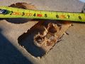 Using a wrong milling strategy, MDF tend to frezzle
 -
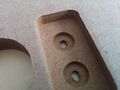 The same thing, just using a different strategy, almost no frezzling (just at the 3mm pocket in the center)


But milling MDF has some pitfalls:
- Mill the depest holes first. If you remove the hard cover of the MDF plate, the internal structure will not hold very good...
- MDF tends to frezzle, if the facings are removed. Reportedly, a very sharp wood plunge mill will reduce the amout of frezzle, use one with 15 degree of spiral angle or less
- The dust of MDF is toxic. Use a vacuum (and respirator)!
- Do not use to slow feed rate! MDF will burn easily.
24000 rpms are probably better, but at this speed the spindle makes a lot of noise. So i decided to use 18000 rpm, which worked quite well. Probably the feedrate could be higher with 24k, but the machine is already in the "orange" zone with 2000 mm/min.
Cutting Speed
or in German "Schnittgeschwindigkeit" is depended on workpiece material, cutter material, cooling, method of milling and many others. The values listed below are just reference values! For a specific project you need to find out your parameters by reading datasheets or even test cuts in the material. If you need to do test cuts, start with the lowest possible value. But do not start to low because the "Spanbreite" needs to be larger than the blade edge radius.
| Material | Cutter | Cooling | Cutting Speed | Feed Rate per Tooth | Comment |
|---|---|---|---|---|---|
| Wood | VHM | No | over 300 (some sources say up to 3000) | ??? | Tested with . Sharp tools and steep spiral angle works best. |
| Aluminium (9-13% Si) | VHM | 300 | 0.06 | From "Praxis der Zerspantechnik" |
![{\displaystyle v_{c}[{\frac {\text{m}}{\text{min}}}]}](https://en.wikipedia.org/api/rest_v1/media/math/render/svg/cca12a48a74b2f69977bd06c3f3dd78b4575f37e)
![{\displaystyle f_{z}[{\frac {\text{mm}}{\text{min}}}]}](https://en.wikipedia.org/api/rest_v1/media/math/render/svg/fd884e15d88b8209b60bd507c09722001626ea7c)

This document from Sorotec is quite useful: Sorotec Cutting Speeds. But beware! These values are a rule of thumb and we might not be able to reproduce the results on our machine! Yet another word to datasheets: The values are usually given for a tool's lifetime of 15 minutes! Yes, you read right only fifteen minutes! If you want to keep for cutters for a longer time, then do not use those values.
A rule of thumb is the following: The lower the Youngs modulus (E-Module) of a material, the sharper the tools must be, a more rigid setup is required, heavy feeds and slow speeds produce better results and abundant cooling is required. This is due to the yielding of the material during cutting. A very stiff material will not yield under the cutting force. A good example is the difference between polymeres and aluminium. Polymeres have low E-Modules (in the range of a few GPa) where aluminium has a E-Module of 70GPa. When cutting polymeres, the main problems are melting and smearing of the material, when using the same parameters as for aluminium.
In the next two plots, you can see how cutting speed, feed per tooth and the resulting revolution speed and feed rate interact. The limits of the plot are also the limits of our machine. You will notice, that it is not possible with our setup to reach higher values for f_z than 0.35 and the cutting speed is limited to about 600m/min - which is only useful in wood anyways.


| From | Variable | Description | Beschreibung | Unit | Formular |
|---|---|---|---|---|---|
| milling cutter | Cutter diameter | Fräserdurchmesser | |||
| Number of Teeth | Anzahl der Schneiden | ||||
| material specific | Feed per Tooth / Chipload per Tooth | Vorschub pro Schneide | |||
| (Surface) Cutting Speed | Schnittgeschwindigkeit | ||||
| calculated | Feed Rate | Vorschub | |||
| revolutions per minute | Drehzahl | ||||
| defined by process and maximum load of machine |
Infeed | Tiefenzustellung | |||
| Sidewards Feed | Seitenzustellung | ||||
| for time considerations | Material Removal Rate | Zeitspanvolumen |


Note for the English terms: It looks like they are not as precise defined as in German. The German terms are explained in "Praxis der Zerspanungstechnik" by Jochen Dietrich (DOI: 10.1007/978-3-658-14053-3), but I could not find any English reference book on that topic yet --Reox (Diskussion) 10:06, 4. Aug. 2018 (CEST)
These values are connected to each other. There are two main formulars to calculate and . To have cutting speed in m/min instead of mm/min you need to divide by 1000. A third formular gives you an estimation how much cm³ you can remove per minute, called .
Typically you choose a specific milling cutter for the job and lookup the values for the material. The process parameter are bound by the maximum load the machine can handle (See for example Why can't I mill steel in the CNC?) and of course by the workpiece you want to produce.
The cutting speed in the datasheet of a cutter is often calculated for a service time ("Standzeit") of 1 hour, sometimes only 15 minutes! That means if you mill with the exact parameters that are posted in the datasheet, the cutter will be unuseable after only a short amount of time. You really need to check for what service time, the datasheet is written. Often the manufacturer will not tell you, so assume the worst (which is 15min).
Milling Strategy
Or: conventional milling vs climb milling. There are two ways of cutting material: either the spindle direction is the same as the feed or not. The first method is called climb milling or in German Gleichlauffräsen, where the latter one is called conventional milling or in German Gegenlauffräsen. As our feedspindles have some backlash, we can not really make use of climb milling on our machine! Of course, you can use climb milling for finnishing passes, if you remove very less material. In all other cases use conventional milling. If you mill with the full cutter diameter, there is no difference of the feed direction though, as half the cutter is in climb mode, the other half is in conventional mode.
If you are milling outer contours you have to go counter-clockwise, on inner contours you need to go clockwise to use conventional milling.
How to
FreeCAD Path-Workbench
Siehe CNC-Workshop von ripper, mehr Infos folgen.
Ganz wichtig:
Post Processor für die CNC-Fräse von Github holen. Hat zB automatischen Drehzahlhochlauf inkludiert.
CamBam Mini HowTo

Sehr wichtige Parameter
- CutIncrement - Wie tief geht die fraese in einem schritt
- TargetDepth - Wie tief soll er insgesammt gehen. Die operation wird dann in TargetDepth/cutIncrement unterschritte zerlegt. ACHTUNG dieser wert muss negativ sein damit die fraese rein fraest.
- CutFeedrate Wie schnell wird horizontal gefraest (mm/sec)
- PlungeFeedrate Wie schnell wird in das Material hineingetaucht (mm/sec)
- ToolDiameter Durchmesser des Fraeskopfes damit CamBam die pfade so berechnen kann dass nach dem fraesen die gewuenschte form entsteht
Weitere Parameter
- InsideOutside Falls man die Outline verkehrt herum geyeichnet hat kann man mit dieser option innen und aussen umdrehen (einfach mal ausprobieren)
Related Pages
- CNC - Software Infos und so..
- PCB_CNC Use the CNC to create PCBs
- Geil-o-mat/History History of the CNC
- Geil-o-mat/Future Future of the CNC
- Benutzer:Reox/CNC, Benutzer:Chrysn/Flausch-o-mat User Notes
Subpages:
Formeln zum Berechnen von Zustellung, Umdrehungsgeschwindigkeit usw.
Technical Details
See this other Page for even more technical things: CNC Mill Technical Stuff
A CNC mill like the dear Geil-O-Mat has three axis that can be moved independently. A spindle with a mill cutter typically removes material.

Each axis is driven by one (Y and Z) or two (X) stepper motors. Basically, theses motors can only rotate in 1.8 degree steps, and hence no secondary encoder is needed for the machine knowing its current location. By a trick called "microstepping", currently the resolution is increased to 1/8 of 1.8 degrees. As the stepper leads in to a "Zwillings-Trapezgewindespindel", the rotation is transformed into linear motion, one revolution= 6mm. Warning: If there is too much force for the motor to move one step, it skips the step, typically failing also in subsequent movements, resulting in an ugly noise, and shift in the positioning.
The motors are connected to a driver device, which sits on top of the whole machine. It creates the strong currents for the stepper drivers, out of signals from the PCs parallel port.
Hence, the computer has to send signals telling which axis should move one step forward or backward at a given instance. This can/is done by a software called "LinuxCNC". It is open source, and the thread doing this parallel port communications is using the patched real time Linux-kernel.
There are some GUIs for LinuxCNC, the most relevant is "AXIS", which graphically displays the current machine position, the paths it should travel the track history, and further stuff. Also manual movement can be performed.
The language to specify the movement of the machine is called "GCODE". Some of its statements are starting with G01,or G00, hence the name. A simple Gcode can look like this:
; i am a comment
F100; move with 100mm/min while cutting
G0 Z10; fast move to Z-coordinate 10
G1 Z0; drill down until Z=0 with the speed given by the Feedrate
G1 X10; move to the new location X10 while cutting
G0 Z10; and back up with large speed.
M30; end program
One can do a lot of things, e.g. have variables (#1=10), and do loops , evaluate mathematical expressions (G1 Z[#1*2] ). So basically, real hackers write gcode by hand, while Chuck Norris sends movement commands to the steppers. However, as we are all lacy, and things can get quite complicated, there exists software to convert 3d/2d CAD files, grayscale depthmap images, 3d-stl objects and other things into Gode. This is often called "CAM"-Software.
If you have a 2d-cad file (e.g. dxf) and specify depths for some areas that should be milled away, one speaks of 2.5D-CAM. This is performed e.g. by CamBam, or Camexpert.
The biggest trouble is the radius compensation of the milling heads. You always have to cut on a path half a diameter outside of the actual position. For this, there are various workflows. In Gcode, one can tell specify if one wants to cut left, right or directly on the actual path. This is called cutter radius compensations. Its a pain in the ass. Hence, often one uses no such thing, but either draws directly the offsetted lines in CAD, or has some software like cambam, which does this compensation and outputs already compensated "paths". The drawback of both methods is that one can not change the diameter of the cutter without recreating the gcode.
In the Gcode compensation, a "tool table" can be used. Each cutter is index by a number, and in the table the diameters and other things are specified. The other variant is to define the radius compensation directly. For our CNC machine a tool table is not useful, but on machines which have automated tool changer it can store all offsets and positions in the tool changer.
The current machine's state is given by a coordinate triple, and some states (emergency swich, spindle speed, ...). The machine coordinate system is defined by the now automated homing routine. Thereafter, one can move the machine to a location, and "touch off", giving explicit coordinates for this location. Thereby the working coordinate system is defined. This is also the system displayed in Axis, However, in the background, the machine still works in the home-coordinate system for checking its movement limits. Clever!