TassimoHack: Unterschied zwischen den Versionen
Pk (Diskussion | Beiträge) (nice one from c3o (cf. plob)) |
|||
| Zeile 62: | Zeile 62: | ||
== Alarm Clock Internals == | == Alarm Clock Internals == | ||
| − | FIXME: | + | FIXME: Oscilloscope picture |
An alarm clock was chosen at random. | An alarm clock was chosen at random. | ||
| Zeile 79: | Zeile 79: | ||
This microcontroller has an internal 4 MHz oscillator, 6 I/O ports and a built-in A/D converter for analog input purposes. | This microcontroller has an internal 4 MHz oscillator, 6 I/O ports and a built-in A/D converter for analog input purposes. | ||
| + | FIXME: Original tassimo picture | ||
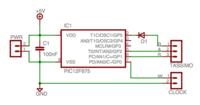
[[Bild:Tassimo-schematic.png|thumb|right|200px|Eagle schematic]] | [[Bild:Tassimo-schematic.png|thumb|right|200px|Eagle schematic]] | ||
| Zeile 95: | Zeile 96: | ||
For simplicity of the toolchain, we decided to program the firmware in assembly. | For simplicity of the toolchain, we decided to program the firmware in assembly. | ||
| − | FIXME: | + | FIXME: Toolchain, programming (PICkit2) |
== Installation == | == Installation == | ||
| Zeile 104: | Zeile 105: | ||
[[Bild:Tassimo-port.jpg|thumb|right|200px|Alarm input port]] | [[Bild:Tassimo-port.jpg|thumb|right|200px|Alarm input port]] | ||
| + | |||
| + | FIXME: Installed-by-the-bed picture | ||
| + | |||
| + | == Source Code & Schematics == | ||
| + | |||
| + | Source code and schematics are available under [http://www.gnu.org/copyleft/gpl.html GNU GPL]: | ||
| + | |||
| + | [[Bild:TassimoHack-0.9.tgz]] | ||
[[Kategorie:Life_Hacks]] | [[Kategorie:Life_Hacks]] | ||
[[Kategorie:WhateverLab]] | [[Kategorie:WhateverLab]] | ||
[[Kategorie:Projekte]] | [[Kategorie:Projekte]] | ||
Version vom 2. März 2007, 00:34 Uhr
WTF?

- Do you often have problems getting up in the morning?
- Have you realized that aquiring more self-dicipline is simply too hard?
- Have you tried placing the alarm clock at the other end of the bedroom, just to find yourself bringing your pillow when turning it off and continue sleeping on the floor?
It's time to toss another technical solution at this: Wire the alarm clock to a coffee machine and wake up to a cup of fresh coffee within an arm's reach.
Tassimo Overview
Tassimo is an automatic and relatively small coffee machine. The retail price is ca. EUR 130, and it can be picked up at virtually any supermarket here in Wien.
The Tassimo requires only two button presses to brew coffee once the
machine has been prepared. A quick run-down of the preparations
follows:
Preparation:
- Turn machine OFF
- Fill water tank
- Insert coffee disc and close lid
- Add cup
- Turn machine ON -> standby LED will be on
Brew:
- Press Start -> aufheizen LED will blink
- Wait up to 1 minute while heating -> automatik LED will then turn on
- Press Start -> Brewing will start, the automatik LED will blink
- Wait while brewing. The automatik LED will turn off and the manuell LED will turn on when finished.
Cleanup:
- Open lid and remove coffee
Tassimo Internals
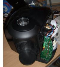
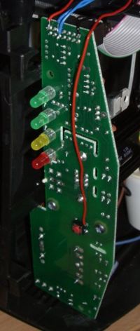
Interesting contact points on the Tassimo internal circuit board:
| JP1, pin 1 | 5V |
| JP1, pin 3 | standby |
| JP1, pin 7 | automatik |
| JP1, pin 12 | GND |
| SW1: | start/stop button |
Alarm Clock Internals
FIXME: Oscilloscope picture
An alarm clock was chosen at random. Opening the clock revealed the buzzer connector. An oscilloscope was connected to analyze the signal: When the alarm is off, the signal stays constant at ca. 1.2 volts (battery power from an old, single-cell battery). When the alarm sounds, a waveform is present, with an amplitude reaching from ca. 0 volts to ca. 4 volts.
Circuit Design
Our I/O needs, based on the above dissections are:
- 1 (analog) input to sense the alarm
- 2 digital inputs to sense the standby and automatik LEDs
- 1 digital output to trigger the Start button
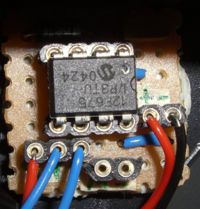
For this purpose, we decided to use a PIC12F675 in a 8-pin package. This microcontroller has an internal 4 MHz oscillator, 6 I/O ports and a built-in A/D converter for analog input purposes.
FIXME: Original tassimo picture
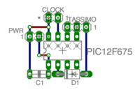
The circuit was then build and soldered onto a strip-board.
Firmware
The firmware is quite simple. In essence, this is what should be done:
- Wait until the alarm goes off (analog input raises above 3 volts)
- Press Start button
- Wait until the Automatik light goes off
- Press Start button again
For simplicity of the toolchain, we decided to program the firmware in assembly.
FIXME: Toolchain, programming (PICkit2)
Installation
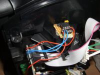
To avoid having wires stick out of the Tassimo and make the alarm clock optional, a small input port was attached on the back side of the machine. The two pins are ground and alarm signal.
FIXME: Installed-by-the-bed picture
Source Code & Schematics
Source code and schematics are available under GNU GPL:
