Metaboard/2010 activities: Unterschied zwischen den Versionen
Chrysn (Diskussion | Beiträge) (→Current status: working prototype) |
Chrysn (Diskussion | Beiträge) (→Other Links: olek.tk's tips) |
||
| (9 dazwischenliegende Versionen von 2 Benutzern werden nicht angezeigt) | |||
| Zeile 41: | Zeile 41: | ||
* Board voltage: 3.3V (originally 5V, but 3.3V gives cleaner USB communication and should save power in the sensor units) | * Board voltage: 3.3V (originally 5V, but 3.3V gives cleaner USB communication and should save power in the sensor units) | ||
* Flashing sensors using serial interface using the [[Metaboard/2010 activities/6-pin auto-detecting programming]] | * Flashing sensors using serial interface using the [[Metaboard/2010 activities/6-pin auto-detecting programming]] | ||
| + | * Power supply: "18650" (z.B. von [http://www.dealextreme.com dealextreme]) | ||
=== Random implementation detail notes === | === Random implementation detail notes === | ||
| Zeile 78: | Zeile 79: | ||
* [[Metaboard/2010 activities/Hacksession 2010-10-14]]: LEDs are important | * [[Metaboard/2010 activities/Hacksession 2010-10-14]]: LEDs are important | ||
* [http://sense.reox.at/usbbb/prototype/ 2010-10-29]: built first (and working!) version of the usbBB, a USB connector for breadboards which is our first attempt in PCB milling | * [http://sense.reox.at/usbbb/prototype/ 2010-10-29]: built first (and working!) version of the usbBB, a USB connector for breadboards which is our first attempt in PCB milling | ||
| + | * [http://sense.reox.at/usbbb/prototypev3/ 2010-11-10]: Prototype v3 (without USB Port and LF33CV because just ordered them) | ||
| + | * [http://sebastian.arttis.net/main.php?g2_itemId=10481 2011-03-15]: Hacking arround with [[HP54645D_Mixed-Signal_Oscilloscope]] and see whats going on at sck, sdi, sdo and irq | ||
| + | * [http://sense.reox.at/rfm12/ 2011-03-20]: WOOOHOOO got something over the air, used mostly code from [http://www.tahina.priv.at/electronics.html#index2h1 here]... also: datasheet gone wrong... port with ANT marking is in real GND, ANT Port is next to it! | ||
| + | * 2011-03-25: If it works at 5V and doesn't at 3.3V, just try adding a startup delay. Hacking on based on [http://jeelabs.net/projects/cafe/repository/show/RF12 jeelabs' RF12 library] now. | ||
== Resources == | == Resources == | ||
| Zeile 91: | Zeile 96: | ||
* [http://www.embedds.com/interfacing-rfm12-transceiver-module/ RFM12 transceiver module]: a board with ATmega8, with the RFM12 completely connected (see [http://comwebnet.co.funpic.de/RFM12/Projekt-RFM12-Tranceiver.pdf schematics]) | * [http://www.embedds.com/interfacing-rfm12-transceiver-module/ RFM12 transceiver module]: a board with ATmega8, with the RFM12 completely connected (see [http://comwebnet.co.funpic.de/RFM12/Projekt-RFM12-Tranceiver.pdf schematics]) | ||
* [[Benutzer:Mihi/Programming-attiny45-mit-arduino]]: programming arduinos with arduinos | * [[Benutzer:Mihi/Programming-attiny45-mit-arduino]]: programming arduinos with arduinos | ||
| + | * The vKeyBoard mentioned on [http://pjrc.com/teensy/projects.html the Teensy project page] seems to do exactly the USB-to-USB trick described above, but using two [http://pjrc.com/teensy/ Teensy] boards, which use an ATMega32U4 each. These chips might even provide a way to get the desired functionality in one chip by using vUSB to get a second USB port and optocouplers USB-side, but they are rather difficult to work with unless preassembled in a teensy. | ||
=== Physical resources === | === Physical resources === | ||
| Zeile 109: | Zeile 115: | ||
** [http://www.mikrocontroller.net/articles/RFM12 RFM12 on mikrocontroller.net]: german description of RFM12 commands | ** [http://www.mikrocontroller.net/articles/RFM12 RFM12 on mikrocontroller.net]: german description of RFM12 commands | ||
** [http://www.mikrocontroller.net/articles/AVR_RFM12 AVR RFM12 on mikrocontroller.net] | ** [http://www.mikrocontroller.net/articles/AVR_RFM12 AVR RFM12 on mikrocontroller.net] | ||
| + | ** [http://olek.tk/en/rfm12.php olek.tk's RFM12 tips], including the magical FE reset command | ||
* DMX: | * DMX: | ||
** [http://www.maxim-ic.com/datasheet/index.mvp/id/1111 Maxim RS485 controllers] | ** [http://www.maxim-ic.com/datasheet/index.mvp/id/1111 Maxim RS485 controllers] | ||
| Zeile 121: | Zeile 128: | ||
* General Arduino related stuff | * General Arduino related stuff | ||
** [http://www.ladyada.net/library/arduino/bootloader.html Arduino Hacks: Bootloader Hacks]: maybe this could show how to integrate the bootloader with the program so we can upload new software from USB w/o physically touching the device | ** [http://www.ladyada.net/library/arduino/bootloader.html Arduino Hacks: Bootloader Hacks]: maybe this could show how to integrate the bootloader with the program so we can upload new software from USB w/o physically touching the device | ||
| + | * USB: | ||
| + | ** [http://www.beyondlogic.org/usbnutshell/usb1.shtml USB in a NutShell]: a good summary of the USB spec | ||
| + | * 18650 / LiPo charging: | ||
| + | ** [http://batteryuniversity.com/learn/article/charging_lithium_ion_batteries battery university on Li-Ion batteries] | ||
* Metalab projects: | * Metalab projects: | ||
Version vom 21. Oktober 2011, 21:07 Uhr
As of September 2010, reox and chrysn are about to build some microcontroller stuff, partially based on the metaboard, and centered around home automation.
People who want to participate are invited to join, even if there is just a small overlap between the things we build!
Some current files are in gitorious (clone using "git clone git://gitorious.org/metaboard/metaboard.git metaboard").
Goals
- Physical goals:
- Build remote sensors that monitor room parameters; those should be as cheap as possible (<10€)
- Build a base station for those sensors that can be used both for receiving and programming the sensors
- Build a version of said base station that can also control that can emit DMX signals
- Learning goals:
- Planning a physical computing device from standard components
- Physically creating the devices
- Community interaction goals:
- Document the learning experience
- Enhance tools used
- Create a version of metaboard that can be edited using free tools
Random extension ideas
- IR transceiver for integration with TV or universal remotes
- Measuring water level in indoor fountains
- wireless or opto-coupled USB-to-USB keyboard/mouse or serial device
- could double as a replacement for serial terminal / null modem connections (violates USB specs, but should work with Linux)
Implementation
- Microcontrollers: Atmel AVR (ATmega and ATtiny; chosen for availability of existing infrastructure (gcc, arduino libraries) and widespread use in similar applications)
- PCB implementation: single sided PCB with no SMD components
- Board base: metaboard (at least for the base station)
- RF communication: ISM band using HopeRF RFM12B
- Computer communication: V-USB (works with metaboard, is cheap and much cooler than relying on serial port emulation)
- Layouting software: gEDA seems to be the best free schematic and PCB editor
- Board voltage: 3.3V (originally 5V, but 3.3V gives cleaner USB communication and should save power in the sensor units)
- Flashing sensors using serial interface using the Metaboard/2010 activities/6-pin auto-detecting programming
- Power supply: "18650" (z.B. von dealextreme)
Random implementation detail notes
- Some AVR boards have onboard temperature sensors that don't block an external pin. Given sufficiently low power output and sensor precision, those could be used for monitoring room temperature.
- The RFM12B modules feature low voltage detection. This could save some analog circuicy and pin on boards fed off battery w/o a voltage regulator.
Parts
for the base board (metaboard + DMX + RF12)
this is partially outdated due to the change to 3.3V board voltage
- a 5V voltage regulator (7805)*
- capacitors: 100nF, 22pF (2x)
- clock crystal: 16MHz (for other frequencies, check the V-USB hardware considerations)
- diodes: 1N4004*, 3V6 (2x)
- jumper pads of length 3 (2x) and 2
- "negative jumper pads" (or whatever they are called) of length 2, 4, 6 and 8 (2x)
- polarized capacitors: 10µF (2x) (*: 1x)
- power jack*
- resistors: 68Ω (2x), 100Ω*, 1.5kΩ, 1MΩ
- RS485 driver: SN78176a*
- push button
- ATMega168 (or 328)
- RFM12 DIP*
- USB-B connector
- DIP sockets: 8*, 28
- socket for RFM12 DIP (2mm 2x4)*
The components marked with * are optional in the first stage of building the board, which will be about getting to know V-USB.
Current status
- Metaboard/2010 activities/Hacksession 2010-09-17: bootstrapped a an ATmega168 via an existing arduino on a breadboard
- Metaboard/2010 activities/Hacksession 2010-09-20: arduino style programming on the breadboard
- Metaboard/2010 activities/Hacksession 2010-10-14: LEDs are important
- 2010-10-29: built first (and working!) version of the usbBB, a USB connector for breadboards which is our first attempt in PCB milling
- 2010-11-10: Prototype v3 (without USB Port and LF33CV because just ordered them)
- 2011-03-15: Hacking arround with HP54645D_Mixed-Signal_Oscilloscope and see whats going on at sck, sdi, sdo and irq
- 2011-03-20: WOOOHOOO got something over the air, used mostly code from here... also: datasheet gone wrong... port with ANT marking is in real GND, ANT Port is next to it!
- 2011-03-25: If it works at 5V and doesn't at 3.3V, just try adding a startup delay. Hacking on based on jeelabs' RF12 library now.
Resources
Existing similar solutions
(We could probably directly go for some of them, but doing it all ourselves gives more flexibility and a learning experience.)
- JeeLabs: Arduino compatible boards running on 3.3V with RFM12B modules and a plug system for sensor components
- cm's wireless temperature and humidity sensor with USB interface: one of the V-USB example projects, pretty close to what we want to build
- Arduino DMX shield: pretty straight forward DMX master
- iPhone and DMX: Arduino with DMX and ethernet shield
- RFM12 transceiver module: a board with ATmega8, with the RFM12 completely connected (see schematics)
- Benutzer:Mihi/Programming-attiny45-mit-arduino: programming arduinos with arduinos
- The vKeyBoard mentioned on the Teensy project page seems to do exactly the USB-to-USB trick described above, but using two Teensy boards, which use an ATMega32U4 each. These chips might even provide a way to get the desired functionality in one chip by using vUSB to get a second USB port and optocouplers USB-side, but they are rather difficult to work with unless preassembled in a teensy.
Physical resources
We hope to be granted access to Metalab / WhateverLab resources for physically creating the boards (PCB etching (or milling?), solder station, parts repository / order collections), and will approach metalabbers as soon as we know what we want at all.
Other Links
- AVR
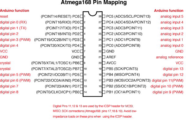
- Arduino/ATmega168 pinout: Labeled schematic of ATmega168 with complete pin names and arduino references (pin mapping)
- AVR fuse calculator: A web application to choose fuse settings, includes avrdude output
- wikibooks on Atmel AVR: Good introduction and overview of features
- ATmega168 datasheet as linked from Bauteilsortiment
- RFM12:
- RFM12B supplier website
- RFM12 tutorial
- RFM12 vs RFM12B: the differences
- RFM12 on mikrocontroller.net: german description of RFM12 commands
- AVR RFM12 on mikrocontroller.net
- olek.tk's RFM12 tips, including the magical FE reset command
- DMX:
- Maxim RS485 controllers
- SN75176BP data sheet: the TI RS485 transceiver
- DMX512 introduction
- gEDA/PCB:
- gEDA symbols: library of gEDA symbols and PCB footprints
- PCB documentation: not as outdated as the copyright notice makes you think
- gsch2pcb tutorial: how to get a .pcb file from a .sch file and how to update it
- gEDA symbol creation: creating custom symbols, includes footprint naming convention
- editing PCB footprints
- General Arduino related stuff
- Arduino Hacks: Bootloader Hacks: maybe this could show how to integrate the bootloader with the program so we can upload new software from USB w/o physically touching the device
- USB:
- USB in a NutShell: a good summary of the USB spec
- 18650 / LiPo charging:
- Metalab projects: