MK802II A20: Unterschied zwischen den Versionen
Amir (Diskussion | Beiträge) (Die Seite wurde neu angelegt: „This page is a rough guide on how to get linux running on the MK802II_A20 android hdmi stick. ==== Name ==== I'm actually not sure how to call this device si…“) |
Amir (Diskussion | Beiträge) |
||
| Zeile 6: | Zeile 6: | ||
Another good candidate for a name would be "QT800" since that is printed on the pcb (an there is a very similar hdmi dongle out there call "reko qt800") | Another good candidate for a name would be "QT800" since that is printed on the pcb (an there is a very similar hdmi dongle out there call "reko qt800") | ||
| − | ==== Serial ==== | + | ==== Serial Communication ==== |
The fist thing i needed is getting serial communication with the device working. | The fist thing i needed is getting serial communication with the device working. | ||
I didn't know where and if the rs232 pins are exposed on the pcb. Also some of the promising looking test pads were pretty tiny. | I didn't know where and if the rs232 pins are exposed on the pcb. Also some of the promising looking test pads were pretty tiny. | ||
So i soldered cables to those test pads and hooked them up to an oscilloscope. | So i soldered cables to those test pads and hooked them up to an oscilloscope. | ||
| + | |||
| + | [[Image:Cables_mk802ii_a20.jpeg]] | ||
| + | |||
| + | And those are the RX and TX pins i found. For ground i soldered to the base of the hdmi plug. | ||
| + | |||
| + | [[Image:Serial_mk802ii_a20.jpg]] | ||
Version vom 12. Juni 2014, 16:43 Uhr
This page is a rough guide on how to get linux running on the MK802II_A20 android hdmi stick.
Name
I'm actually not sure how to call this device since it is sold on ali express under many names. I choose MK802II_A20 since that's the name of the uboot dram config that was closest to the actually config i'm using (see "Bootloader" below). Another good candidate for a name would be "QT800" since that is printed on the pcb (an there is a very similar hdmi dongle out there call "reko qt800")
Serial Communication
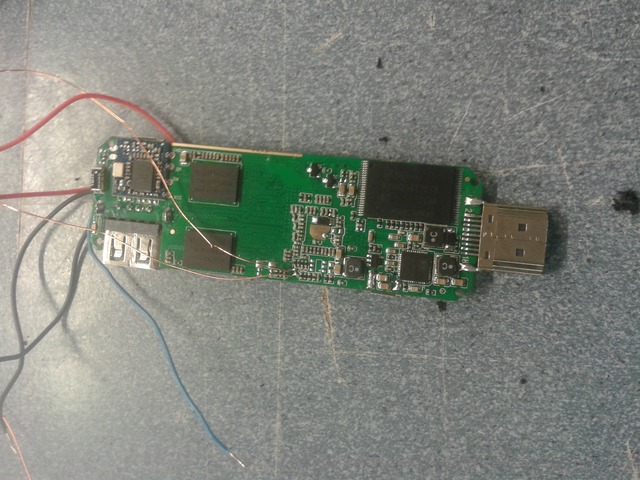
The fist thing i needed is getting serial communication with the device working. I didn't know where and if the rs232 pins are exposed on the pcb. Also some of the promising looking test pads were pretty tiny. So i soldered cables to those test pads and hooked them up to an oscilloscope.
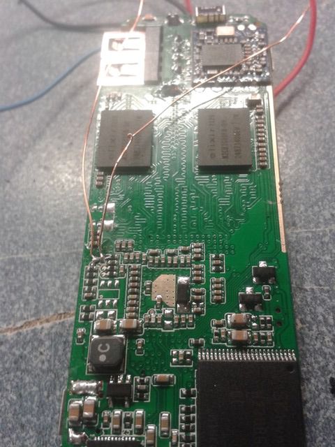
And those are the RX and TX pins i found. For ground i soldered to the base of the hdmi plug.

