C64DTV: Unterschied zwischen den Versionen
| (4 dazwischenliegende Versionen von einem anderen Benutzer werden nicht angezeigt) | |||
| Zeile 38: | Zeile 38: | ||
== Connectors == | == Connectors == | ||
| − | I have fitted the connectors onto the casing of the joystick, using a dremel and a glue gun (NB! no gaffa was used in this project :). | + | I have fitted the connectors onto the casing of the joystick, using a dremel and a glue gun (NB! no gaffa was used in this project :)). |
Connectors, seen from the front: | Connectors, seen from the front: | ||
| Zeile 91: | Zeile 91: | ||
== Connecting to the PCB == | == Connecting to the PCB == | ||
| − | |||
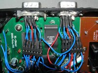
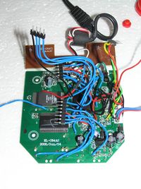
All soldering should be done on the backside of the PCB. Note that some soldering points are located under the rubber buttons. For flexibility, I built internal connectors to easier be able to disconnect and debug the connectors. | All soldering should be done on the backside of the PCB. Note that some soldering points are located under the rubber buttons. For flexibility, I built internal connectors to easier be able to disconnect and debug the connectors. | ||
| − | [[Bild:internal1.png|thumb|200px|Keyboard && disk connectors]] | + | {| |
| − | [[Bild:internal2.png|thumb|200px|Joystick connectors]] | + | |[[Bild:solderpoints.png|thumb|200px|soldering points on PCB]] |
| − | [[Bild:internal3.png|thumb|200px|PCB with connectors]] | + | |[[Bild:internal1.png|thumb|200px|Keyboard && disk connectors]] |
| + | |- | ||
| + | |[[Bild:internal2.png|thumb|200px|Joystick connectors]] | ||
| + | |[[Bild:internal3.png|thumb|200px|PCB with connectors]] | ||
| + | |} | ||
<p> | <p> | ||
| Zeile 106: | Zeile 109: | ||
{| | {| | ||
|[[Bild:regulator_schem.png|200px|regulator schematics]] | |[[Bild:regulator_schem.png|200px|regulator schematics]] | ||
| − | + | ||
|[[Bild:regulator.png|200px|+5V voltage regulator]] | |[[Bild:regulator.png|200px|+5V voltage regulator]] | ||
| − | + | ||
|[[Bild:regulator_conn.png|200px|regulator connection]] | |[[Bild:regulator_conn.png|200px|regulator connection]] | ||
|} | |} | ||
== Result == | == Result == | ||
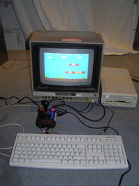
| − | [[Bild:system.jpg| | + | [[Bild:system.jpg|left|thumb|200px|Modded joystick in action]] |
== TODO/ideas == | == TODO/ideas == | ||
| Zeile 119: | Zeile 122: | ||
* Reprogram the built-in flash memory with an updated game collection | * Reprogram the built-in flash memory with an updated game collection | ||
* Add a memory card reader which supports reading disk images stored on a CF/SD/XD/USB-stick/whatever memory card. | * Add a memory card reader which supports reading disk images stored on a CF/SD/XD/USB-stick/whatever memory card. | ||
| + | |||
| + | For comments, questions, ideas etc., contact [[Benutzer:MariusKintel|Marius]] | ||
[[Kategorie:WhateverLab]] | [[Kategorie:WhateverLab]] | ||
| − | [[Kategorie: | + | [[Kategorie:Projekte]] |
Aktuelle Version vom 23. Januar 2013, 23:41 Uhr
WTF?
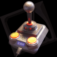
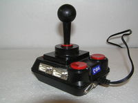
The C64 Direct-to-TV, called C64DTV for short, is a single-chip implementation of the Commodore 64 computer, contained in a joystick with 30 built-in games (C64_Direct-to-TV). The games are stored on a built-in 2MB flash memory.
The joystick can be bought at Conrad (but I've also seen it at Zielpunkt) for ~25 Euros.
This is an amazing piece of hardware, but comes with a few weaknesses:
- Only one joystick, no support for two-player games
- A limited selection of games
- The quality of the joystick itself is far from the gold standard (Competition Pro)
..so let's remedy this:
Project Overview
The goal is to remedy the stated weaknesses by doing the following:
- Add ports for two external joysticks => support multi-player gaming and we can use better joysticks
- Add connectors for a PS/2 keyboard and a 1541 compatible disk drive => load games from 5.25" floppy disks
Part List
Parts, Conrad part numbers and total price in Euros:
- 2x SUB D-Stiftleiste 9 polig 742066 1.14
- 1x Mini-DIN Steckdose 738422 1.73
- 1x DIN Einbaubuchse 6-polig 738166 1.20
- 2x Buchsenleiste 32-polig 740438 2.30
- 1x 5V 7805 Spannungsregler 179205 0.65
- 1x 100 uF Elko (we've got more of these in the lab)
- 2x 100 nF Kondensator (we've got more of these in the lab)
Connectors
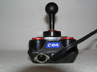
I have fitted the connectors onto the casing of the joystick, using a dremel and a glue gun (NB! no gaffa was used in this project :)).
Connectors, seen from the front:
Joystick
|
Keyboard
|
Disk drive
| ||||||||||||||||||||||||||||||||||||
Connecting to the PCB
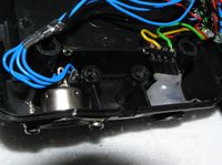
All soldering should be done on the backside of the PCB. Note that some soldering points are located under the rubber buttons. For flexibility, I built internal connectors to easier be able to disconnect and debug the connectors.
Power Supply
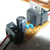
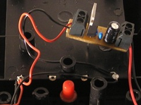
When connecting peripherals to the joystick, it will not be able to run from batteries anymore, so I'm running it from a DC power supply. Since the joystick assumes a 5V power supply, I've build a 5V voltage regulator circuit. The regulator is connected to the output of the battery pack (see picture). NB! Remove batteries before connecting external power.

|
|
|
Result
TODO/ideas
- Reprogram the built-in flash memory with an updated game collection
- Add a memory card reader which supports reading disk images stored on a CF/SD/XD/USB-stick/whatever memory card.
For comments, questions, ideas etc., contact Marius
