HSC2011/Building your own EduBuzzer: Unterschied zwischen den Versionen
Chrysn (Diskussion | Beiträge) K (better subpage fake) |
Chrysn (Diskussion | Beiträge) (building instructions part 1) |
||
| Zeile 1: | Zeile 1: | ||
<small>< [[HSC2011]]</small> | <small>< [[HSC2011]]</small> | ||
| + | |||
| + | == Requirements == | ||
In order to build an EduBuzzer, you'll need | In order to build an EduBuzzer, you'll need | ||
| Zeile 13: | Zeile 15: | ||
Image:Atomic.svg| and a copy of the EduBuzzer software and hardware description from the [[HSC2011/Download instructions|project download page]]. | Image:Atomic.svg| and a copy of the EduBuzzer software and hardware description from the [[HSC2011/Download instructions|project download page]]. | ||
</gallery> | </gallery> | ||
| + | |||
| + | == Hardware == | ||
| + | |||
| + | === The main board === | ||
| + | |||
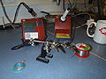
| + | [[Image:Build_edubuzzer.gif|thumb|If your hardware-fu is stong, the board will assemble iself]] | ||
| + | |||
| + | For etching the main board, you'll find all required files in the `hardware/gerber` subdirectory of the [[HSC2011/Download instructions|repository]], or you can directly use the Eagle files in `hardware`. For building an ergonomic buzzer, use the `buzzer` files. | ||
| + | |||
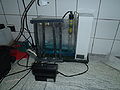
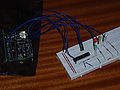
| + | [[Image:Hsc2011_prototype_pcb3.jpg|thumb|The arduino shield -- comparison between the prototyping and our custom shield]] | ||
| + | |||
| + | As an alternative (to try it out with less effort), use the `arduino_schield` files -- with them, you need fewer components, and get an arduino shield you can plug onto an Arduino compatible device. If you are good at soldering and want to get going with what is present in a typical hackerspace (at least, [[Bauteilsortiment|in the metalab]]), you can produce the same circuit even on a prototyping shield. | ||
| + | |||
| + | Solder in all the components as described in the [[HSC2011/Hardware#Part list|part list]], starting with the big parts. We recommend to use sockets for both the ATMega328 and the RFM12B module, as they are prone to overheating from inexperienced soldering, and as there is no programming header exposed for the ATMega. (Updates can be flashed using a serial bootloader, but if you break something, things get tricky.) Other parts to take care of: | ||
| + | |||
| + | * R10 -- don't install it, it's for adjusting the compatibility behavior with respect to Arduino's DTR handling, and | ||
| + | * SW5 -- connect using about 5cm of cable, as the switch is installed in a dedicated slot in the case. | ||
| + | |||
| + | '''Checkpoint''': You can try out the hardware immediately by flashing `firmware/ioexample.hex` onto an ATMega328 (works even with the ATMega328 built in in an Arduino -- just flash it as normal, take out the chip put it into the buzzer's socket). The device will: | ||
| + | |||
| + | * when the first button is pressed, blink through all LEDs, | ||
| + | * when the second button is pressed, make sounds while toggling through the LEDs, | ||
| + | * when the third button is pressed, fade the RGB LED around all colors, | ||
| + | * when the last button is pressed, send commands over radio, | ||
| + | * when an iButton is inserted, show a hash of its ID on the LEDs, and buzz six times. | ||
| + | |||
| + | When the IO-example is flashed on two devices, the second should respond to the radio commands and cycle through its own LEDs. | ||
[[Category:HSC2011]] | [[Category:HSC2011]] | ||
Version vom 1. Mai 2011, 22:00 Uhr
< HSC2011
Requirements
In order to build an EduBuzzer, you'll need
a bunch of electronic parts you can obtain from your supplier of choice,
equipment for etching a two sided PCB (as an alternative, you can order it just as well -- we didn't etch ours),
a rapid prototyper (3D printer, e.g. a makerbot),
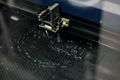
a lasercutter for cutting 5mm transparent acryl sheet (if unavailable, a rapid prototyper with transparent substrate will work as well),
soldering equipment,
screws with driver (what made you guess our hardware design is not 100% finished in that part?),
a programmer for AVR microcontrollers (any AVR microcontroller with a bootloader will do, especially an Arduino -- c.f. the Arduino ISP tutorial) with appropriate software, e.g. avrdude,

and a copy of the EduBuzzer software and hardware description from the project download page.


Hardware
The main board

For etching the main board, you'll find all required files in the `hardware/gerber` subdirectory of the repository, or you can directly use the Eagle files in `hardware`. For building an ergonomic buzzer, use the `buzzer` files.

As an alternative (to try it out with less effort), use the `arduino_schield` files -- with them, you need fewer components, and get an arduino shield you can plug onto an Arduino compatible device. If you are good at soldering and want to get going with what is present in a typical hackerspace (at least, in the metalab), you can produce the same circuit even on a prototyping shield.
Solder in all the components as described in the part list, starting with the big parts. We recommend to use sockets for both the ATMega328 and the RFM12B module, as they are prone to overheating from inexperienced soldering, and as there is no programming header exposed for the ATMega. (Updates can be flashed using a serial bootloader, but if you break something, things get tricky.) Other parts to take care of:
- R10 -- don't install it, it's for adjusting the compatibility behavior with respect to Arduino's DTR handling, and
- SW5 -- connect using about 5cm of cable, as the switch is installed in a dedicated slot in the case.
Checkpoint: You can try out the hardware immediately by flashing `firmware/ioexample.hex` onto an ATMega328 (works even with the ATMega328 built in in an Arduino -- just flash it as normal, take out the chip put it into the buzzer's socket). The device will:
- when the first button is pressed, blink through all LEDs,
- when the second button is pressed, make sounds while toggling through the LEDs,
- when the third button is pressed, fade the RGB LED around all colors,
- when the last button is pressed, send commands over radio,
- when an iButton is inserted, show a hash of its ID on the LEDs, and buzz six times.
When the IO-example is flashed on two devices, the second should respond to the radio commands and cycle through its own LEDs.