Blinkentunnel 2.0: Unterschied zwischen den Versionen
M68k (Diskussion | Beiträge) |
Pete (Diskussion | Beiträge) K (Textersetzung - „ente“ durch „Usergraveyard“) |
||
| Zeile 75: | Zeile 75: | ||
* [[Benutzer:Overflo|Overflo]] - idea, electronics, soldering, firmware | * [[Benutzer:Overflo|Overflo]] - idea, electronics, soldering, firmware | ||
* [[Benutzer:Redplanet|redplanet]] - stein des anstosses, soldering | * [[Benutzer:Redplanet|redplanet]] - stein des anstosses, soldering | ||
| − | * [[ | + | * [[User:Usergraveyard|Usergraveyard]] - soldering, assembly line |
* [[Benutzer:Min|min]] - soldering, assembly line | * [[Benutzer:Min|min]] - soldering, assembly line | ||
* [[Benutzer:Nioram|nico]] - QLC+ setup, effects, installation | * [[Benutzer:Nioram|nico]] - QLC+ setup, effects, installation | ||
Aktuelle Version vom 19. September 2018, 19:28 Uhr
| Blinkentunnel 2.0 | |
| |
| Gestartet: | 17.11.2016 |
| Involvierte: | overflo + lots of helpers |
| Status: | completed |
| Beschreibung: | artsy fartsy blinky thingy |
| Shutdownprozedur: | |
| Zuletzt aktualisiert: | 2018-09-19 |
Blinkentunnel 2.0
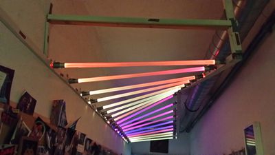
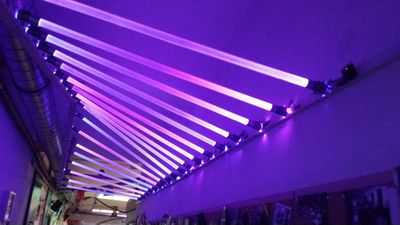
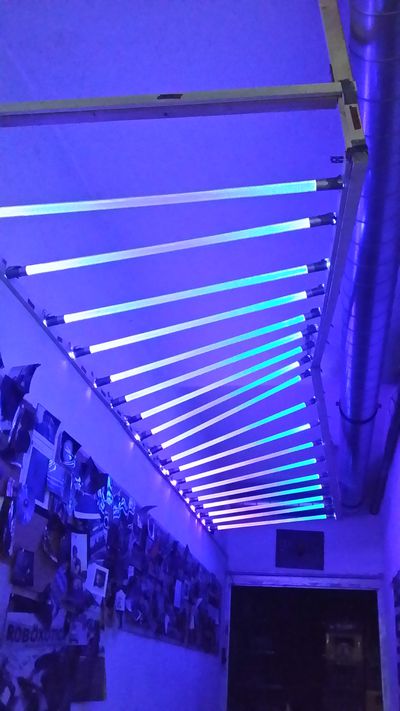
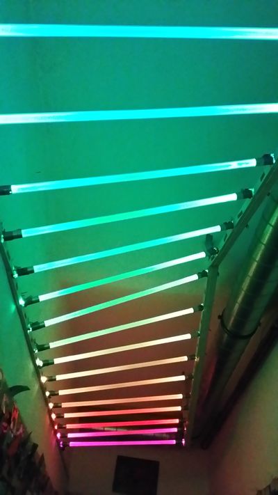
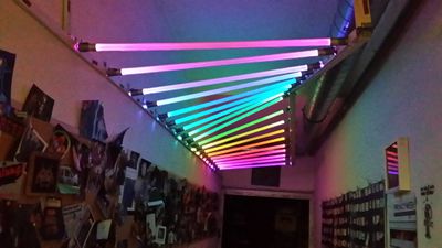
- The successor of the famous Blinkentunnel project
- Located at the passway between our mainroom and the entrance room
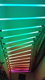
- There are 18 acryl sticks mounted to the ceiling, with 12mm WS2801 Pixels mounted on each side and shining inwards
- They are controlled from an ESP8266 custom made PCB with a custom firmware that supports ARTNET see Blinkybutton
How
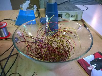
We built the original Blinkentunnel 7 years ago using Shiftbrites and an Arduino based on the Atmega168.
Today we got fully integrated digitally controllable leds and WIFI based boards the size of a thumbnail.
When redplanet tried to fix the old installation it became clear that we should replace the leds and that led to also replacing the ancient controller with something modern.
So Overflo spent a long weekend designing a little PCB and writing some custom firmware for the ESP8266 based board he made and called the result Blinkybutton The setup Boots in ~1.2 seconds and diplays a classic rainbow animation.
It tries to connect to the WLAN and if that fails it opens its own Accesspoint called ARTNET-NODE_26_C6
When you connect there it opens a captive portal configuration interface where you can setup the parameters like:
- WLAN to connect to
- Password
- ARTNET universe ID (currently set to 0)
- ARTNET OFFSET (currently set to 0)
- Static IP Address (unconfigured , it uses DHCP)
- Static Gateway (unconfigured , it uses DHCP)
- Static Netmask (unconfigured , it uses DHCP)
Once it is connected to the network it continues to display the rainbow animation but it also waits for ART-net data to arrive and display that instead of the rainbow.
It returns to displaying the rainbow when there is no data received for >5 minutes.
Media
How to ART-net
- Install QLC+
- Connect to metalights WiFi (password: metalights)
- Configure QLC+ so it outputs on the 192.168.88.255 address
- Define a 18x2 matrix fixture
- Use the matrix-functions on this fixture
- Combine with all kinds of other effects, inputs, masks and what not..
- All done
People involved
- Overflo - idea, electronics, soldering, firmware
- redplanet - stein des anstosses, soldering
- Usergraveyard - soldering, assembly line
- min - soldering, assembly line
- nico - QLC+ setup, effects, installation
- max - soldering, installation
- ripper - installation, parts
- Other people I forgot to mention. Sorry! Please add yourself here
References / Links
- QLC+ Light Controlling Software
- WS2801 Datasheet
- ESP8266 Datasheet
- Blinkybutton @ (hackerspaceshop) TBD
- Artnet
- github FIRMWARE
