Avrprog-metaboard: Unterschied zwischen den Versionen
Cs (Diskussion | Beiträge) (New version, updated docs accordingly) |
|||
| Zeile 82: | Zeile 82: | ||
[[Kategorie:WhateverLab]] | [[Kategorie:WhateverLab]] | ||
[[Kategorie:English]] | [[Kategorie:English]] | ||
| + | [[Kategorie:Arduino]] | ||
Version vom 22. Juni 2008, 16:02 Uhr
What is AVRProg based on Metaboard?
AVRProg is an In System Programmer (ISP) for AVR microcontrollers. It is built on the breadboard area of metaboard.
Features
- Includes two programming sockets for directly programming 8 pin, 20 pin and 28 pin devices, including the popular ATTiny25/45/85, ATTiny2313, ATMega8, ATMega48/88/168/328. [8 pin devices are inserted into 20 pin socket.]
- Generates 1 MHz clock for programming devices which require external clock.
- Simple design, almost no additional components required.
- USBasp and AVR-Doper firmware ported to this hardware, AVRminiProg will follow. A ported version of USBasp is included here, for AVR-Doper please download the original package (>= 2008-04-26) and compile for metaboard.
- Optional power supply for target.
Design Considerations
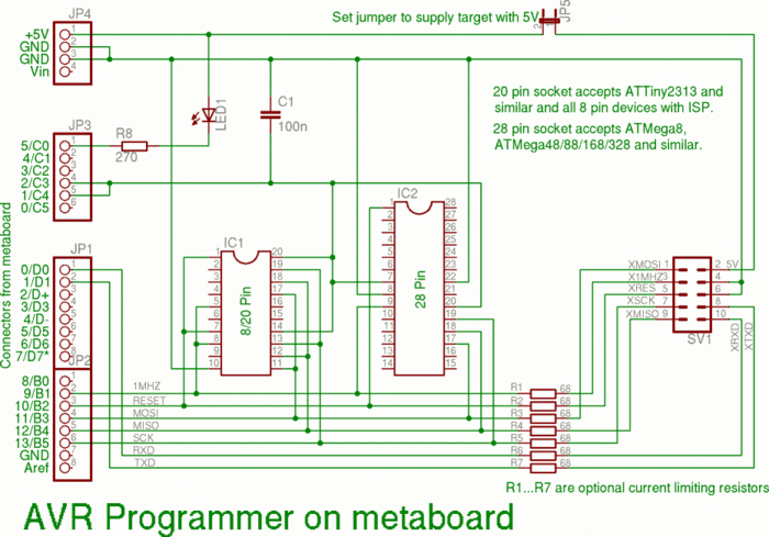
In order to keep this programmer simple, no level converters have been added. This means that the programmer and the target device should be powered at approximately the same voltage. The design allows for optional series resistors in all signal lines leaving the board. These series resistors limit the maximum current and prevent damage should the target device and the programmer be powered at different voltages. With these resistors in place, a certain amount of level conversion can be performed by the AVR's and target's input protection diodes. Programming a target powered at 3.3 V should be possible.
In addition, the design offers an optional power supply for the target. This power supply can be activated with a jumper. Please note that there is NO CURRENT LIMIT in this power supply except the USB host's polyfuse. Make sure that you don't set this jumper if the target is self-powered!
An old style 10 pin ISP socket was used because some of the pins can be used for different purposes. The pin originally intended for an ISP LED on the target carries a 1 MHz clock. This clock can be used as CPU clock if you connect a board with additional programming sockets (e.g. 40 pin, SMD etc). Two of the ground pins from the original assignment have been connected to metaboard's RxD and TxD lines (D0 and D1). When the AVR-Doper firmware is used, these pins can be used to read debug information from the target's UART (if the target provides it, of course).
Power Supply for the on-board programming sockets is switched by two I/O pins. The two pins in parallel provide enough current for programming all supported AVRs. Since they are only active when in programming mode, target devices can be inserted and removed without danger of destruction.

Building the Programmer
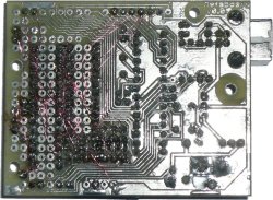
Building the hardware should be straight forward, see the circuit diagram above and the image of the board's copper side on the right. Most components are optional: If you don't want programming sockets, just skip them. If you don't want the ISP connector, skip it and the series resistors. And if you don't want the over-current protection, omit the series resistors.
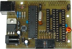
As you can see on the images, metaboard's I/O connectors have been omitted and the signals have been directly wired to the connector pads. A word of warning: Although the circuit is very simple, it involves a lot of wire connections. Don't under-estimate the time required to build this circuit! Expect three hours of work, given a ready-made metaboard.
Once you have the hardware in place, you need to upload the firmware. There are (currently) two choices: USBasp or AVR-Doper.
If you decide for USBasp: The directory "USBasp-firmware" in the distributed package contains a modified version of Thomas Fischl's USBasp. The modifications include the generation of a 1 MHz clock, different I/O pins for USB and the low SCK jumper, different CPU clock and switchable supply for programming sockets. Change to this directory and type
make metaboard
to build the modified firmware. A simple "make main.hex" would build a version for the original USBasp. Then set the "Upload" jumper on metaboard, choose USB for power supply with JP5, connect the device to the host and press the reset button to activate the boot loader. Now you can upload the firmware with
make flash
After this final step remove the upload jumper - it is now used to choose between normal (~ 200 kHz) and slow (~ 8 kHz) programming clock. The programming clock must be less than 1/4 of the target's CPU clock.
If you decide for AVR-Doper: Download version 2008-04-26 or later, change to the "firmware" directory and type
make metaboard
To upload the firmware, use
make usbaspload
(this target uses the appropriate options for avrdude).
Download
The latest version is always available from the SVN repository: https://whatever.metalab.at/user/cs/avrprog-metaboard/trunk.
A package with a PNG format circuit diagram can be downloaded here:
| Download: | avrprog-metaboard-1.1.zip |
| avrprog-metaboard-1.0.zip |

