Blinkofant: Unterschied zwischen den Versionen
aus Metalab Wiki, dem offenen Zentrum für meta-disziplinäre Magier und technisch-kreative Enthusiasten.
Zur Navigation springenZur Suche springen| Zeile 66: | Zeile 66: | ||
|- | |- | ||
|} | |} | ||
| + | |||
| + | |||
| + | |||
| + | when connecting ONE single panel the following pins need to be connected on the output side: | ||
| + | |||
| + | PIN 1 -> PIN 8 | ||
| + | PIN 2 -> PIN 3 | ||
Version vom 25. März 2012, 18:49 Uhr
WTF
Recently we got this HUGE led walls.
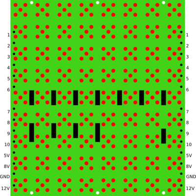
we disassmbled the monster and now we got ~300 led modules
each 8*9 pixels each pixel consisting of 5 leds = 360 red leds / panel times ~300 panels equals 90.000 leds++ :) we dont know how tp power them yet :)
Doku der pins
- POUT EQU CENTRO ;the leftmost module will be connected to the POUT-port
- ATTENTION! The bit positions must not be changed!
- 8V, 5V, 12V, GND sind auf unseren boards NICHT bestückt mit pins.
| pin number | function | unsere kommentaore |
| 1 | data/clock ? comes back out here (rückleitung schebereigster) | wurscht |
| 2 | data/clock ? comes back out here (rückleitung schebereigster) | wurscht |
| 3 | DatLoad EQU 0 ;data bit for loading data and control data | wurscht |
| 4 | ClkRing EQU 1 ;clock for shift left the whole line | CLOCK !! |
| 5 | ClkLoad EQU 2 ;clock for shift left & loading all selected modules | wurscht |
| 6 | ClkBlink EQU 3 ;clock for blinking (0...off, 1...on) | selektrierte spalte blinken |
| 7 | ClkSteu EQU 4 ;clock for shift left & load control data from DatLoad | wurscht |
| 8 | DatRing EQU 5 ;data bit for loading data during ClkRing | DATA !! |
| 9 | Reset EQU 6 ;clear all control data | wurscht |
| 10 | OnOff EQU 7 ;turn on/off the whole display (0...off, 1...on) | turns off ALL the leds when pulled to ground |
when connecting ONE single panel the following pins need to be connected on the output side:
PIN 1 -> PIN 8 PIN 2 -> PIN 3

