PCB CNC: Unterschied zwischen den Versionen
Reox (Diskussion | Beiträge) |
Reox (Diskussion | Beiträge) |
||
| Zeile 84: | Zeile 84: | ||
First of all you will create a PCB in a program called pcb. Then you will export gerber files from the pcb and generate ngc files with pcb2gcode. These ngc files can be read by linuxcnc. | First of all you will create a PCB in a program called pcb. Then you will export gerber files from the pcb and generate ngc files with pcb2gcode. These ngc files can be read by linuxcnc. | ||
For a Single Layer PCB you will run Steps 1,2,3,4 and 6 for a dual Layer you will run 1 to 6. | |||
=== Create the PCB === | === Create the PCB === | ||
[[Datei:Pcb layer groups.png|thumb|400px|grouping of layers in pcb]] | |||
gEDA's pcb is a complex tool to work with. It might not be as easy to use as other tools in the first place, but can do everything another tool can do. | gEDA's pcb is a complex tool to work with. It might not be as easy to use as other tools in the first place, but can do everything another tool can do. | ||
Normaly you will design the PCB as you would do normaly, just remember that you need some extra clearance because of the cutter diameter. | Normaly you will design the PCB as you would do normaly, just remember that you need some extra clearance because of the cutter diameter. | ||
| Zeile 93: | Zeile 96: | ||
* All Top Layers go to one group | * All Top Layers go to one group | ||
* Outline is one group | * Outline is one group | ||
=== pcb2metalab.sh === | === pcb2metalab.sh === | ||
| Zeile 104: | Zeile 104: | ||
git clone pcb2metalab from here: https://github.com/reox/pcb2metalab | git clone pcb2metalab from here: https://github.com/reox/pcb2metalab | ||
If you modify the Makefile and run make, it will build all necassary files for you. You can check the output of the gerber files with a tool called gerbv and there are also some png files for debugging. | |||
=== Milling of Bottom Side === | |||
Now its time to go to the CNC and put in the PCB. Load the backside ngc file. Now you need to touch off the workpiece. | |||
Remember now two things: The coordinates in the pcb2metalab generated files are in inch and the PCB is not super flat! | |||
=== Drilling the Bottom Side === | |||
The Next step would be to drill. Because the workpiece is already touched-off, it should go smoothly. | |||
=== Switch Sides === | |||
[[Datei:G10command.jpg|thumb|400px|The math behind the G10 L2 command]] | |||
This step is now crucial for the quality of the dual layer PCB. | |||
== Usage == | == Usage == | ||
Version vom 21. Februar 2015, 21:48 Uhr
Introduction
CNCs can facilitate in the creation of PCBS:
- Manual etching and then using CNC to drill automatically.
- Cutting out the board , to have round PCBs, or similar.
- Automated isolation routing: From a PCB some surface parts are milled away, so that the connection copper area are left isolated.
Currently, all three steps are working on the Geilomat.
For the isolation, there is the normal approach, where all contours of copper areas are milled.
However much faster results can be obtained by milling the minimal path necessary to create the PCB-topology.
Some results are given in the soup of the Geilomat
- 0805 SMD resistors work fine, although the solder locations are not visible any more. (you can use options to generate no voronoi patterns)
- It is possible to have one wire between the 2.54mm piched pins.
- Also 1.27mm pitch SMD chips are usually ok.
- if you are really careful, you can even do HTSSOP (which is pitch 0.65mm) - but this needs proper milling equipment and a very flat surface
Examples
-
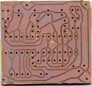
 A normal isolated result.
 -
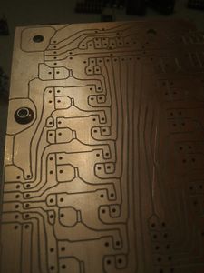
 A rather badly isloated and drilled PCB done on the Geilomat. Short circuiting copper flakes are visible on the center left.
 -
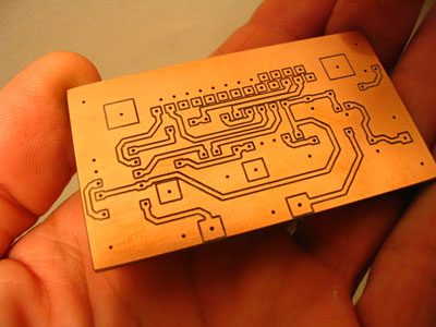 A usually milled PCB, using pcb-gcode eagle plugin. This can be done by metaboard3.sh -tight
 -
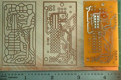 A voronoi milled PCB (left), a normally milled PCB, and a traditional PCB. Source


Time Consumption
For a complete, dense EuroPCB, expect about one hour of total time:
- 10 minutes for preperation, mounting and setup.
- 15 minutes for drilling/cutting.
- 20 minutes for the isolation of the bottom layer.
- 5 minutes for flipping/remounting/aligning
- 20 minutes for the top isolation
- 2 minutes for manual overworking the board.
For an arduino shield, expect about 30 minutes:
- 10 minutes for preperation, mounting and setup.
- 5 minutes for drilling/cutting.
- 5 minutes for the isolation of the bottom layer.
- 5 minutes for flipping/remounting/aligning
- 5 minutes for the top isolation
- 1 minutes for manual overworking the board.
Pros/Cons
Pros:
- Quite Faster than manual UV-exposing, etching and drilling.
- Cool
- No chemicals
- Good for high currents, as wired are wide.
- Cheaper PCB material. (Same area approx 50% the price)
- PCBs of up to 30x20 cm. However, flatness is problematic.
Cons:
- If the board is not mounted completely flat, the isolation might be not deep enough, and hence there are short circuits.
- Sometimes, flakes of copper short circuit neighboring copper areas. Usually at corners. A knife helps.
- Dust.
- Capacity between adjacent copper areas.
- Hotter soldering is required, as there are no thermal pads.
Metaboard*.sh
Metaboard are some bash shell scripts, that will automatically create cnc-paths in the form of gcode files. The starting point is the eagle .brd file. Download of the files: Here
Usage: metaboard3.sh <options> filename filename: eagle brd file to process
-double: create a double sided gcode
-0.8:    use a 0.8mm mill head instead of a 0.6
-tight:  only offset by a distance of 0.3 mm
-filled: the eagle board file has a filed dimension area instead of lines
It calls a couple of external programs:
- Eagle: to output the gerber files of the top and bottom layer
eagle: to call an ulp-program "drillbernhard.ulp" that outputs the drilling and cutting paths.- Eagle: to output the excellon drill files.
Visolate: To create the isolation paths. We use an unreleased version, that is scriptable.- Meanwhile, pcb2gcode was adopted and is used.
- grecode To mirror the board for second side. (Grecode was created especially for metaboard.sh by --Bkubicek 09:55, 26. Jul. 2010 (CEST))
While these are called, a couple of windows will pop up and hopefully disappear again. only shell output will be produced. you will get some debug images also in the current directory.
Workflow Using gEDA pcb and pcb2gcode
The Workflow using the gEDA suite and a seperate tool called pcb2gcode is well tested in the Metalab.
First of all you will create a PCB in a program called pcb. Then you will export gerber files from the pcb and generate ngc files with pcb2gcode. These ngc files can be read by linuxcnc.
For a Single Layer PCB you will run Steps 1,2,3,4 and 6 for a dual Layer you will run 1 to 6.
Create the PCB

gEDA's pcb is a complex tool to work with. It might not be as easy to use as other tools in the first place, but can do everything another tool can do. Normaly you will design the PCB as you would do normaly, just remember that you need some extra clearance because of the cutter diameter.
There is an extra step you need to do now. You need to group the layerers in a specific way:
- All Bottom Layers go to one group
- All Top Layers go to one group
- Outline is one group
pcb2metalab.sh
is a fork of the metaboard script. while it was stripped down to the very basics, it now only works with gEDA pcb files. Because of many chnges in the pcb2gcode tool, some things are now completly different than it was before! Be aware that now some files are generated with pre- and postamble, some are not. Please check and double check the generated g-code files before milling. e.g. there was a bug that the last line was a G53 G0 Z0, which mean on our CNC that the millhead would not retract but go down to the very bottom!
git clone pcb2metalab from here: https://github.com/reox/pcb2metalab
If you modify the Makefile and run make, it will build all necassary files for you. You can check the output of the gerber files with a tool called gerbv and there are also some png files for debugging.
Milling of Bottom Side
Now its time to go to the CNC and put in the PCB. Load the backside ngc file. Now you need to touch off the workpiece. Remember now two things: The coordinates in the pcb2metalab generated files are in inch and the PCB is not super flat!
Drilling the Bottom Side
The Next step would be to drill. Because the workpiece is already touched-off, it should go smoothly.
Switch Sides

This step is now crucial for the quality of the dual layer PCB.
Usage
The workflow splits into the following points:
- Preperation: create an eagle brd file, copy it
- Metaboard*.sh: create the gcode files for the geilomat
- For the most current worflow use metaboard3.sh . It will require a 0.6 mm mill head, which is the best, as small IC holes are possible, and the tool length is so small that little sidewards forces are created. Hence, mill speed is larger than for 0.8mm tools.
- Setup:
- mount the board in the geilomat using double sided sticky tape.
- On the flat milled wood area.
- Which should be de-dusted first.
- Double sided tape should not overlap, as this creates 0.1mm height difference.
- Insert a suitable tool. Either a sharp Gravierstichel .

- EMC-setup: home the machine "home all", "touch off"/set coordinate system so milling will be on the actual board
Bottom layer:
- Isolation-milling: use the *back.ngc file created by metaboard3.sh
- drilling: use the *drill*.ngc file created by metaboard3.sh
- and cutting: use the *outline*.ngc file created by metaboard3.sh.
For single sided boards, the process stops here. Double sided boards are more sophisticated:
- Flipp the board, mounting it in any usefull position.
- Top layer:
- note down two drill hole coordinates from the drill file, in mm units.
- navigate using the joypad to the holes location on the flipped mounted PCB. Write down the coordinates of the special holes.
- call "grecode -align x1 y1 x2 y2 X1 Y1 X2 Y2 *front*.ngc > tmp.ngc" to rotate and shift. Maybe you have to change the signs of the x1 and x2, depending of the pcb2gcode version you use.
- Loading the tmp.ngc file just created
- check if the gcode is now aligned with the pcb.
- Isolate the top.
Removing the boards works best by using a twist motion around the z-axis. A brush should be nearby to clean the grooves.
Hints
VIAS


Milled vias form no automatic connection between top and bottom. You can solder them using a small copper wire. Or the magical Kupferhohlnieten.
If you change the diameter of your vias to 0.8, you can use the 0.6 inner diameter "Kupferhohlnieten". if you have a double side-connected pin of you 0.7 mm you might want to use a 1mm hole, to use the larger "hohlnieten", where you can then insert a 0.7mm pin.
Pins of through-hole mounted devices also do not form automatic top-bottom connections. This especially frustrating with the eagle autorouter, because I found no way of turning this off. Sometimes you can compensate by soldering also on the top side of the part, but very often there is really no space for that. Best thing is to manually overwork the board in eagle.

Routing
While the eagle autorouter tries to bundle wires closely together, for voronoi shaped pcbs, this is not so optimal. You can still use the autorouter, however I would recommend it only on the bottom layer. I use a 12.5 mil routing grid usually, and * for bottom N/A for top. Then I move the wires around, so that the sidewards distance is maximized. This is done by having arbitrary diagonals, and successively moving outer wires further outside.

Mounting Holes
Currently PCB2Gcode does not respect mounting holes, meaning that it would grow the wires possibly in a way that two different signals could be short-circuited by the screw. To prevent this, place a bottom wire-arc around the screw. Then it gets it's own "pad".
Isolation Distances
If you happen to work with larger voltages, you need isolated gaps on the PCB. I would do that by drawing a filled polygon on the bottom layer, or a group of overlapping or connected wires, as if the isolation were a wire. After the milling, I would use a sharp knife to lift the copper from the board at a corner, and peel it off. If you know the trick, it works quite well.
