Blinkofant: Unterschied zwischen den Versionen
Pk (Diskussion | Beiträge) typos, foo |
|||
| Zeile 1: | Zeile 1: | ||
== WTF == | == WTF? == | ||
Recently we got this | Recently we got this *huge* LED walls. | ||
We disassmbled the monster and now we got ~300 LED panels | |||
Each of the 8*9 pixels consists of 5 LEDs = 360 red LEDs per panel<br /> | |||
300 panels equals 90.000 LEDs++ :) | |||
we | |||
we don't know how to power them yet :) | |||
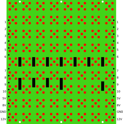
[[Bild:ledmatrix_doku_open.png|thumb|400px|right| 1 modul]] | [[Bild:ledmatrix_doku_open.png|thumb|400px|right| 1 modul]] | ||
[[Bild:ledmatrix_chained.png|thumb|400px|right| 4 module chained]] | [[Bild:ledmatrix_chained.png|thumb|400px|right| 4 module chained]] | ||
== | == Pinout == | ||
* POUT EQU CENTRO ;the leftmost module will be connected to the POUT-port | * POUT EQU CENTRO ;the leftmost module will be connected to the POUT-port | ||
* ATTENTION! The bit positions must not be changed! | * ATTENTION! The bit positions must not be changed! | ||
* 8V, 5V, 12V, GND | * 8V, 5V, 12V, GND are not equipped with pins | ||
{| border=1 | {| border="1" cellspacing="0" cellpadding="8" width="" style="border-collapse:collapse;" | ||
|+ | |+ | ||
| pin | | '''pin #''' | ||
| function | | '''function''' | ||
| | | '''comments''' | ||
|- | |- | ||
| 1 | | 1 | ||
| data/clock ? comes back out here ( | | data/clock ? comes back out here (Rückleitung Schieberegister) | ||
| wurscht | | wurscht | ||
|- | |- | ||
| 2 | | 2 | ||
| data/clock ? comes back out here ( | | data/clock ? comes back out here (Rückleitung Schieberegister) | ||
| wurscht | | wurscht | ||
|- | |- | ||
| Zeile 63: | Zeile 64: | ||
| 10 | | 10 | ||
| OnOff EQU 7 ;turn on/off the whole display (0...off, 1...on) | | OnOff EQU 7 ;turn on/off the whole display (0...off, 1...on) | ||
| turns off ALL the | | turns off ALL the LEDs when pulled to ground | ||
|- | |- | ||
|} | |} | ||
| Zeile 71: | Zeile 72: | ||
when connecting ONE single panel the following pins need to be connected on the output side: | when connecting ONE single panel the following pins need to be connected on the output side: | ||
pin 1 -> pin 8<br /> | |||
pin 2 -> pin 3 | |||
Version vom 25. März 2012, 22:40 Uhr
WTF?
Recently we got this *huge* LED walls.
We disassmbled the monster and now we got ~300 LED panels
Each of the 8*9 pixels consists of 5 LEDs = 360 red LEDs per panel
300 panels equals 90.000 LEDs++ :)
we don't know how to power them yet :)


Pinout
- POUT EQU CENTRO ;the leftmost module will be connected to the POUT-port
- ATTENTION! The bit positions must not be changed!
- 8V, 5V, 12V, GND are not equipped with pins
| pin # | function | comments |
| 1 | data/clock ? comes back out here (Rückleitung Schieberegister) | wurscht |
| 2 | data/clock ? comes back out here (Rückleitung Schieberegister) | wurscht |
| 3 | DatLoad EQU 0 ;data bit for loading data and control data | wurscht |
| 4 | ClkRing EQU 1 ;clock for shift left the whole line | CLOCK !! |
| 5 | ClkLoad EQU 2 ;clock for shift left & loading all selected modules | wurscht |
| 6 | ClkBlink EQU 3 ;clock for blinking (0...off, 1...on) | selektrierte spalte blinken |
| 7 | ClkSteu EQU 4 ;clock for shift left & load control data from DatLoad | wurscht |
| 8 | DatRing EQU 5 ;data bit for loading data during ClkRing | DATA !! |
| 9 | Reset EQU 6 ;clear all control data | wurscht |
| 10 | OnOff EQU 7 ;turn on/off the whole display (0...off, 1...on) | turns off ALL the LEDs when pulled to ground |
when connecting ONE single panel the following pins need to be connected on the output side:
pin 1 -> pin 8
pin 2 -> pin 3