Blinkenwall.com: Unterschied zwischen den Versionen
Anlumo (Diskussion | Beiträge) |
Anlumo (Diskussion | Beiträge) |
||
| Zeile 39: | Zeile 39: | ||
| 6x200W Power supplies || €203.28 || {{Yes}} | | 6x200W Power supplies || €203.28 || {{Yes}} | ||
|- | |- | ||
| Network cable || | | Network cable || reused || {{No}} | ||
|- | |- | ||
| Computer || ~€40 ? || {{No}} | | Computer || ~€40 ? || {{No}} | ||
Version vom 15. Februar 2017, 16:05 Uhr

Blinkenwall v2
Concept: No glass bricks any more, instead something mounted on in the wall. This simplifies a lot of things and also makes everything a lot more complicated but allows a higher resolution.
Current State of Project
Already Done
- Ordered & received panels
- Created an aluminium frame for mounting the panels, the power supply and the receiver card
- Mounted everything onto the frame
Current Status: Hardware is running.
TODO
- Mount it into the wall.
- Install an ARM-board for sending video data to the wall.
- Install a relay into the wall to turn off the power supplies when they're not needed to avoid wasting too much power.
Current State of the Budget
| Item | Price | Delivered |
|---|---|---|
| 60 panels | €476.28 | ✔ |
| Controller cards + cables | €146.97 | ✔ |
| Shipping for panels + controllers | €283.91 | ✔ |
| Import tax + toll + fees | €201.16 | ✔ |
| 6x200W Power supplies | €203.28 | ✔ |
| Network cable | reused | ✘ |
| Computer | ~€40 ? | ✘ |
| Mounting frame | ? | ✔ |
| Diffusing plate | ~€200 ? | ✔ |
HUB75
One idea: Using the HUB75 panels available for cheap from China.
The goal is to have a resolution roughly equivalent to the original Gameboy (160x144). Note that it had an aspect ratio very close to square, which is not feasible on the wall. Thus, the goal is to have at least 160 pixels horizontally, and whatever is suitable vertically (96?).
HUB75 panels are classified by their pixel distance. The distance chosen for this calculation is P10, which means 10mm distance (in both dimensions). This is the lowest density available for indoor panels.
The old Blinkenwall has a size of 1920x1100mm, but the new one can be significantly taller and a bit wider. HUB75 panels usually have a resolution of 32x16, thus 320x160mm.
The chosen panel layout is 6x9, which means 6*320mm = 1920mm horizontally and 9*160mm = 1440mm. The resulting resolution is 192x144, which exceeds the target of 160x144.
The price for the panels alone would be about €710 here, including some spares (6*9=54, the price is for 60 panels) and shipping. EUSt (import tax) is not included, and might add another €150 to it.
The product description says that the panels draw 15W maximum, so it should be about 860W in total (all pixels bright white). The merchant recommends 1000W in total. Note that this can be reduced by using a black background for animations (which was done with the old version as well). The panels need 5V (so, PC power supplies can't be used, since they can only supply most of their power on 12V). Multiple power supplies of 200W each could be used for this, and the LRS-200-5 looks like a good contender for that. As of the time of this writing, they cost €33.88 per piece, and six of them would fit very well (one per column). A single more powerful power supply is not a good idea, since they tend to use loud fans.
Mounting
The panels have mounting holes in the back, constructing a frame for them is trivial. Cooling is a bit of a concern, since a lot of power is dissipated. A diffusing pane (polycarbonate?) should be mounted in front of the panels so the pixels become larger. Multiple 5V power supplies could be used for powering the whole system. Unlike the old solution, it should be possible to turn it off!
anlumo has tested a single one of these panel running for a longer time and experienced no heat rise, so maybe cooling isn't necessary at all.
Controller
This is where the real challenge comes in. These panels do not have a controller built in, your have to PWM the rows and columns yourself. The connection is called HUB75, although this is not an official standard per se. There are plenty of explanations available on the web, and it's not very complicated. However, if you want to have more than the primary colors, you can't use an Arduino for it, since it's not fast enough (colors have to be centrally PWMed). You have to send a steady ~7MHz signal, which usually can only be produced by FPGAs.
Panels can be chained, but this reduces the color fidelity (because the input signal is limited to about 7MHz, no matter how many panels are connected. Reduced bandwidth per panel means fewer colors). Also note that these panels need gamma correction, because the perception of LEDs is far from linear. Thus, you need a color depth of about 10bits to get 8bits of real colors. There are a few tricks to alleviate this, for example you can reduce the frame rate to allow more colors, or you can do temporal interpolation. It's a bit of black magic.
Thus, the easiest solution is to connect to each panel individually.
Luckily, this is not the first project to come across this issue. Thus, there are controllers available for this, like this one (featuring a Spartan 6 FPGA, surprise surprise). anlumo is working on a custom Zynq 7020-based solution for controlling these panels, but that project is in the planning stages right now.
The controllers expect RAW Ethernet packets (they do not use TCP or UDP). The vendor expects people to buy their much more expensive DVI-to-Ethernet adapters (for example TS901), and so the protocol itself is not documented. Some nice folk have discussed a reverse engineering attempt in a forum (in German), but it's not fully done yet. If this protocol can be reimplemented, a regular SBC could generate it directly via its Ethernet interface (Raspberry Pi not recommended, since its Ethernet interface is very limited).
The sending cards have a serial interface for setup, which you only need in the beginning and to change the brightness of the display. They supply a DVI input port (HDMI compatible) for the image data which could be connected to any SBC, even the already existing Raspberry Pi.
Blinkenwall..
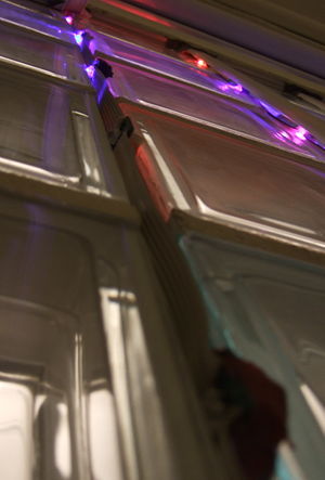
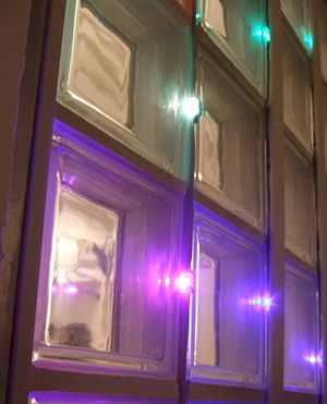
- is the wall between our mainroom and the library
- in this wall are 9x5=45 glassbricks installed
- next to every glassbrick there is one RGB-led with a pretty neat chip attached
- these presoldered boards are called Shiftbrite
- they are currently controlled from an arduino this may change soon for something with more computational power :)
- Click here to draw something nice on the wall!!
How
SVN with current software https://whatever.metalab.at/projects/blinkenwall
We just connected the Arduino to a fonera 2202 over serial.
Now its possible to stream data for display to the blinkenwall using your favourite webbrowser.
Lessons learned:
- one can simply connect RX/TX from fonera to arduino
- no stty in default openwrt busybox build
- openwrt building is an fairly easy task
- replacing the busybox binary on a live system during operation is insane and possible! :)
Reference
Who
- Overflo - electronics, soldering, webinterface, fonera setup
- Wizard23 - help with electronics, basic software setup
- Metaz - arduino library software for shiftbrites
- Nex arduino software for webinterface streaming
- Mactux CSS + iphone webinterface
- Natano .C program to decode webinterface streaming files
Blinkenwall v1.5
Now with ~30 fps and network mode! Go to http://blinkenwall.in.metalab.at/ to activate network mode and send your P6 PPM frames to port 1337/tcp. Make sure that all your frames are exactly 146 bytes in size or you'll risk graphics glitches at higher frame rates.
Who
Lessons learned
- netcat has fixed-length 8K RX/TX buffers.
- The Arduino Duemilanove resets on DTS low (the IDE uses that to reset before programming).
- The Arduino Serial class implements an RX ringbuffer of 128 bytes. Patch the Arduino SDK to adjust this to your needs; RX_BUFFER_SIZE in hardware/arduino/cores/arduino/HardwareSerial.cpp.
- mkfifo(1) is neat when opening ttyUSB* devices leads to an Arduino reset.
Applications
- blinkblink -- old-school animations
- blinkenfft -- real-time audio FFT
- mplayer -vo blinkenwall -- watch movies in a stunning resolution of 9x5
Upgrade to Raspi
Georg and WSys replaced the Fonera/Arduino with a Raspi. Networking capability was restored later by sqrt2.
To stream to the Blinkenwall from your computer, open http://10.20.30.26/cgi-bin/togglesocket.cgi and wait for the test frame to appear, then send RGB data for the 45 pixels as before, but without the PPM header (9*5*3 = 135 bytes per frame). Open the URL again to switch back to animations.
Wiring
Since the Raspi got accidentally disconnected and there was confusion on how to wire it up again, here is how:
- Look at the Raspi model B P1 header pin configuration
- Think of the wires of the ribbon cable connecting to the wall as numbered from R1 to R6, where R1 is the red wire and R6 is the blue wire. Connect the orange wires labeled 2 to 5 to the corresponding wires R2 to R5.
- The big power supply has two wires, a dark blue one and a grey one. Connect the dark blue wire to the blue wire (R6) on the ribbon cable.
- Connect the other connector on the dark blue wire to a ground pin on the Raspi, e.g. pin 6.
- Connect orange wire 2 to pin 23 (SCLK) on the Raspi.
- Connect orange wire 3 to pin 18 (GPIO24) on the Raspi.
- Connect orange wire 4 to pin 22 (GPIO25) on the Raspi.
- Connect orange wire 5 to pin 19 (MOSI) on the Raspi.
- Connect the red wire on the ribbon cable to the big power supply's grey wire (labeled 1).
Videos
First Blinkenwall
Blinkenwall after resurrection at Hackathon_8
Photos
 |
 |
 |
Various Links
- Sample effect - https://whatever.metalab.at/user/meta/blinkenwall/WallSample
- SVN with current software https://whatever.metalab.at/projects/blinkenwall
- http://blinkenwall.com