Blinkenwall.com: Unterschied zwischen den Versionen
Wikis (Diskussion | Beiträge) |
Anlumo (Diskussion | Beiträge) |
||
| (42 dazwischenliegende Versionen von 11 Benutzern werden nicht angezeigt) | |||
| Zeile 1: | Zeile 1: | ||
[[Datei:Blinkenwall_logo_001.png|left|300px|Blinkenwall Logo]] | |||
[[Blinkenwall.com/history|Blinkenwall v1 Historic Page]] | |||
[[Blinkenwall.com/future|Blinkenwall v3 Future Plans]] | |||
= | = Blinkenwall v2 = | ||
Concept: No glass bricks any more, instead something mounted <s>on</s> <font color="#FF0000;">in</font> the wall. This <s>simplifies a lot of things and also</s> <font color="#FF0000;">makes everything a lot more complicated but</font> allows a higher resolution. | |||
[https://hackaday.io/project/19876-blinkenwall-v2 Hackaday.io Project Link ] | |||
== Current State of Project == | |||
=== Already Done === | |||
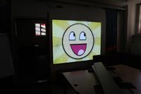
[[Bild:Blinkenwall.JPG|200px|left]] | |||
* Ordered & received panels | |||
* Created an aluminium frame for mounting the panels, the power supply and the receiver card | |||
* Mounted everything onto the frame | |||
* Mounted the frame into the wall. | |||
* [[ToxBlinkenwall]] | |||
* [https://metalab.at/wiki/ToxBlinkenwall#share_Youtube_links_to_Blinkenwall_via_Android_App Android App] | |||
* Fix the power setup. | |||
* Install an ARM-board for sending video data to the wall. | |||
* Install a relay into the wall to turn off the power supplies when they're not needed to avoid wasting too much power. | |||
* Implement shadertoy. | |||
* Implement online video playback. | |||
* Implement emulation (Gameboy Color). | |||
* Implement poetry wall. | |||
Current Status: Hardware is running, video is showing up, software is half finished. | |||
== | === TODO === | ||
* | * Install the network cable into the patch panel. | ||
* [ | * Other emulators like NES? | ||
* Integrate VNC or other screenshare | |||
* Better shadertoy: | |||
** Editing existing scripts, including version history | |||
** Thumbnails in the gallery | |||
** Support for textures | |||
* Frontend rewrite with [https://yew.rs/ Yew]? | |||
== Current State of the Budget == | |||
{| class="wikitable" | |||
|- | |||
! Item !! Price !! Delivered | |||
|- | |||
| 60 panels || €476.28 || {{Yes}} | |||
|- | |||
| Controller cards + cables || €146.97 || {{Yes}} | |||
|- | |||
| Shipping for panels + controllers || €283.91 || {{Yes}} | |||
|- | |||
| Import tax + toll + fees || €201.16 || {{Yes}} | |||
|- | |||
| 6x200W Power supplies || €203.28 || {{Yes}} | |||
|- | |||
| Network cable || reused || {{Yes}} | |||
|- | |||
| Computer || ~€40 ? || {{No}} | |||
|- | |||
| Mounting frame || ? || {{Yes}} | |||
|- | |||
| Diffusing plate || ~€200 ? || {{Yes}} | |||
|} | |||
== | == HUB75 == | ||
The idea was to use cheap China LED panels that use a connection usually called HUB75. It's a 1/8 scan protocol that's not really documented, but easy to use. The panels do not have a controller, and so need to be PWMed using something fast like an FPGA. [https://learn.adafruit.com/32x16-32x32-rgb-led-matrix/ Adafruit has a tutorial about using these types of panels.] | |||
The goal was to have a resolution roughly equivalent to the original Gameboy (160x144). Note that it had an aspect ratio very close to square, which is not feasible on the wall. Thus, the resulting resolution is 192x144. | |||
HUB75 panels are classified by their pixel distance. The distance chosen for this calculation is P10, which means 10mm distance (in both dimensions). This is the lowest density available for indoor panels. | |||
== | HUB75 panels usually have a resolution of 32x16, thus 320x160mm. The chosen panel layout is 6x9, which means 6*320mm = 1920mm horizontally and 9*160mm = 1440mm. The resulting resolution is 192x144, which exceeds the target of 160x144. | ||
The product description says that the panels draw 15W maximum, so it should be about 860W in total (all pixels bright white). The merchant recommends 1000W in total. Our measurements tell us that a full white wall draws 680W. We used 6x200W power supplies ([http://www.mouser.at/ProductDetail/Mean-Well/LRS-200-5/ LRS-200-5]), so we're well within the limits. | |||
Note that this can be reduced by using a black background for animations (which was done with the old version as well). | |||
== | === Mounting === | ||
The panels have mounting holes in the back, constructing a frame for them is trivial. Cooling is a bit of a concern, since a lot of power is dissipated. A diffusing pane is mounted in front of the panels so the pixels become larger. | |||
=== Controller === | |||
This is where the real challenge comes in. These panels do not have a controller built in, your have to PWM the rows and columns yourself. The connection is called HUB75, although this is not an official standard per se. There are plenty of explanations available on the web, and it's not very complicated. However, if you want to have more than the primary colors, you can't use an Arduino for it, since it's not fast enough (colors have to be centrally PWMed). You have to send a steady ~20MHz signal, which usually can only be produced by FPGAs. | |||
Panels can be chained, but this reduces the color fidelity (because the input signal is limited to about 7MHz, no matter how many panels are connected. Reduced bandwidth per panel means fewer colors). Also note that these panels need gamma correction, because the perception of LEDs is far from linear. Thus, you need a color depth of about 10bits to get 8bits of real colors. There are a few tricks to alleviate this, for example you can reduce the frame rate to allow more colors, or you can do temporal interpolation. It's a bit of black magic. | |||
Luckily, this is not the first project to come across this issue. Thus, there are controllers available for this, like [http://linsn.com/prod_view.aspx?TypeId=12&Id=81&FId=t3:12:3 this one] (featuring a Spartan 6 FPGA, surprise surprise). [[Benutzer:anlumo|anlumo]] is working on a custom Zynq 7020-based solution for controlling these panels, but that project is in the planning stages right now. | |||
The controllers expect RAW Ethernet packets (they do not use TCP or UDP). The vendor expects people to buy their much more expensive DVI-to-Ethernet adapters (for example TS901), and so the protocol itself is not documented. Some nice folk have discussed a reverse engineering attempt in [https://www.mikrocontroller.net/topic/352894 a forum] (in German), but it's not fully done yet. If this protocol can be reimplemented, a regular SBC could generate it directly via its Ethernet interface (Raspberry Pi not recommended, since its Ethernet interface is very limited). | |||
The sending cards have a serial interface for setup, which you only need in the beginning and to change the resolution and scaling of the display. They supply a DVI input port (HDMI compatible) for the image data which could be connected to any SBC. The resolution can be set anywhere from 640x480 to 1920x1080. HDMI does not support the native resolution of 192x144! | |||
== | {{Projekt | ||
|image=Blinkenwall_logo_001.png | |||
|involved=[[Metalab]] | |||
|startdate= | |||
|status=active | |||
|wtf=A wall made of blinken. | |||
|lastupdate= | |||
|hidden=true | |||
}} | |||
[[Kategorie:English]] | |||
[[Kategorie:Hauptraum]] | [[Kategorie:Hauptraum]] | ||
[[Kategorie: | [[Kategorie:Projekte]] | ||
Aktuelle Version vom 21. November 2021, 21:51 Uhr

Blinkenwall v2
Concept: No glass bricks any more, instead something mounted on in the wall. This simplifies a lot of things and also makes everything a lot more complicated but allows a higher resolution.
Current State of Project
Already Done

- Ordered & received panels
- Created an aluminium frame for mounting the panels, the power supply and the receiver card
- Mounted everything onto the frame
- Mounted the frame into the wall.
- ToxBlinkenwall
- Android App
- Fix the power setup.
- Install an ARM-board for sending video data to the wall.
- Install a relay into the wall to turn off the power supplies when they're not needed to avoid wasting too much power.
- Implement shadertoy.
- Implement online video playback.
- Implement emulation (Gameboy Color).
- Implement poetry wall.
Current Status: Hardware is running, video is showing up, software is half finished.
TODO
- Install the network cable into the patch panel.
- Other emulators like NES?
- Integrate VNC or other screenshare
- Better shadertoy:
- Editing existing scripts, including version history
- Thumbnails in the gallery
- Support for textures
- Frontend rewrite with Yew?
Current State of the Budget
| Item | Price | Delivered |
|---|---|---|
| 60 panels | €476.28 | ✔ |
| Controller cards + cables | €146.97 | ✔ |
| Shipping for panels + controllers | €283.91 | ✔ |
| Import tax + toll + fees | €201.16 | ✔ |
| 6x200W Power supplies | €203.28 | ✔ |
| Network cable | reused | ✔ |
| Computer | ~€40 ? | ✘ |
| Mounting frame | ? | ✔ |
| Diffusing plate | ~€200 ? | ✔ |
HUB75
The idea was to use cheap China LED panels that use a connection usually called HUB75. It's a 1/8 scan protocol that's not really documented, but easy to use. The panels do not have a controller, and so need to be PWMed using something fast like an FPGA. Adafruit has a tutorial about using these types of panels.
The goal was to have a resolution roughly equivalent to the original Gameboy (160x144). Note that it had an aspect ratio very close to square, which is not feasible on the wall. Thus, the resulting resolution is 192x144.
HUB75 panels are classified by their pixel distance. The distance chosen for this calculation is P10, which means 10mm distance (in both dimensions). This is the lowest density available for indoor panels.
HUB75 panels usually have a resolution of 32x16, thus 320x160mm. The chosen panel layout is 6x9, which means 6*320mm = 1920mm horizontally and 9*160mm = 1440mm. The resulting resolution is 192x144, which exceeds the target of 160x144.
The product description says that the panels draw 15W maximum, so it should be about 860W in total (all pixels bright white). The merchant recommends 1000W in total. Our measurements tell us that a full white wall draws 680W. We used 6x200W power supplies (LRS-200-5), so we're well within the limits.
Note that this can be reduced by using a black background for animations (which was done with the old version as well).
Mounting
The panels have mounting holes in the back, constructing a frame for them is trivial. Cooling is a bit of a concern, since a lot of power is dissipated. A diffusing pane is mounted in front of the panels so the pixels become larger.
Controller
This is where the real challenge comes in. These panels do not have a controller built in, your have to PWM the rows and columns yourself. The connection is called HUB75, although this is not an official standard per se. There are plenty of explanations available on the web, and it's not very complicated. However, if you want to have more than the primary colors, you can't use an Arduino for it, since it's not fast enough (colors have to be centrally PWMed). You have to send a steady ~20MHz signal, which usually can only be produced by FPGAs.
Panels can be chained, but this reduces the color fidelity (because the input signal is limited to about 7MHz, no matter how many panels are connected. Reduced bandwidth per panel means fewer colors). Also note that these panels need gamma correction, because the perception of LEDs is far from linear. Thus, you need a color depth of about 10bits to get 8bits of real colors. There are a few tricks to alleviate this, for example you can reduce the frame rate to allow more colors, or you can do temporal interpolation. It's a bit of black magic.
Luckily, this is not the first project to come across this issue. Thus, there are controllers available for this, like this one (featuring a Spartan 6 FPGA, surprise surprise). anlumo is working on a custom Zynq 7020-based solution for controlling these panels, but that project is in the planning stages right now.
The controllers expect RAW Ethernet packets (they do not use TCP or UDP). The vendor expects people to buy their much more expensive DVI-to-Ethernet adapters (for example TS901), and so the protocol itself is not documented. Some nice folk have discussed a reverse engineering attempt in a forum (in German), but it's not fully done yet. If this protocol can be reimplemented, a regular SBC could generate it directly via its Ethernet interface (Raspberry Pi not recommended, since its Ethernet interface is very limited).
The sending cards have a serial interface for setup, which you only need in the beginning and to change the resolution and scaling of the display. They supply a DVI input port (HDMI compatible) for the image data which could be connected to any SBC. The resolution can be set anywhere from 640x480 to 1920x1080. HDMI does not support the native resolution of 192x144!
