Nibble++: Unterschied zwischen den Versionen
Anlumo (Diskussion | Beiträge) Keine Bearbeitungszusammenfassung |
Anlumo (Diskussion | Beiträge) |
||
| Zeile 34: | Zeile 34: | ||
; Pincers : As sharp as you can get. Make sure that they're not bent. | ; Pincers : As sharp as you can get. Make sure that they're not bent. | ||
; A soldering mat : Please, don't destroy the table, especially not at Metalab. | ; A soldering mat : Please, don't destroy the table, especially not at Metalab. | ||
; Light! : It really helps, especially with | ; [https://www.youtube.com/watch?v=mvwd13F_1Gs Light!] : It really helps, especially with | ||
; A binocular microscope : You might get away with a magnifying glass if you have good eyesight. | ; A binocular microscope : You might get away with a magnifying glass if you have good eyesight. | ||
Version vom 6. Mai 2019, 19:53 Uhr
| Language: | English |
|---|
| Nibble++ | |

| |
| Gestartet: | 2019-05-06 |
| Involvierte: | Binary Kitchen, anlumo |
| Status: | completed |
| Beschreibung: | Solder challenge not for the faint of heart |
| Shutdownprozedur: | |
| Zuletzt aktualisiert: | 2019-05-06 |
Nibble++
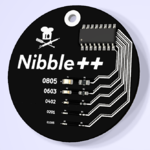
The Nibble++ PCB is a challenge to test how good your fine soldering skills are. It is available at hacker.parts, or you can order the items yourself.
The usual time to complete this challenge is about two hours for experienced solder masters. Make sure that you are in a relaxed and quiet environment when you start.
Basic Premise
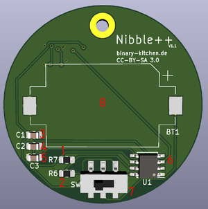
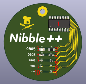
The back side of the PCB contains a coin cell, a power switch and a 555 timer with a few decoupling capacitors. The front side contains a shift register and the real challenge: a series of diode/resistor combinations that get smaller every time. The biggest ones are ginormous 0805 pieces, down to 0603, 0402, 0201 and the smallest size available at the moment, 01005.
What do These Numbers Mean?
They are sizes in hundredth of inches, so 0805 means 0.08x0.05 inch or 2x1.2mm. There are also size specifications in metric units available (0805 in freedom units is 2012 metric), but nobody uses these.
What You Need
The github project linked above has the BOM, but this is the overview:
- The Nibble++ package with all components
- Did I mention hacker.parts?
- The best soldering iron you can get your hands at
- anlumo used a TS100, but the next point is more important:
- An appropriate soldering tip
- The usual instruction is to get the smallest one you can find, but an insider tip is using one with a knife shape:

The reason is that you can adjust the size of the contact area by varying the angle you're using it at. - Solder
- Just the regular 60% Sn 40% Pb stuff with rosin core. Do not lead-free solder!
- Pincers
- As sharp as you can get. Make sure that they're not bent.
- A soldering mat
- Please, don't destroy the table, especially not at Metalab.
- Light!
- It really helps, especially with
- A binocular microscope
- You might get away with a magnifying glass if you have good eyesight.
How to Begin
I can't explain proper soldering on a wiki page, so here is just the way to get handle the Nibble++ specifically:
Solder the backside first (so you can test the front side while you work on it), in this order:
The reason is that you can't reach the smaller parts when the larger ones are on the board. This goes for any PCB.
Note the orientation of two of the parts: The battery holder has a notched side and the smaller IC (the 555 timer) has a dot on pin 1.
To solder the battery holder, apply some solder to both pads on the PCB first, then place the holder, then heat up one pad after the other. When the pad is heated up through the solder tab, everything connects together nicely.
The Real Challenge
Now on to the front side:
The order of 10/11 might seem weird, but there's a reason: the LED at number 10 is cheating. There are no 01005 LEDs, so this is a large 0201 LED. The actual crown jewel of this challenge is the resistor with the final index.
The IC (the shift register) at the top is relatively easy to solder, but mind the orientation. After that, insert the battery and test every time you complete a row. You shouldn't solder a board with power connected, but the switch on the backside disconnects power mechanically, so keeping the battery in is fine on this board.
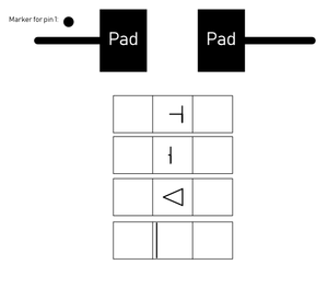
The LEDs in the left column also have an orientation, and that took me the longest to actually get right. Unlike throughhole LEDs, SMD LEDs show their orientation on the backside of the part. You have to flip them, look at them with a microscope, rotate them correctly and then flip them back (making sure that you don't rotate them while flipping them back). Here's the symbol guide:
Closing Words
The creators of this challenge (Binary Kitchen) are asking for feedback on how well it worked. Please contact anlumo and tell your tales, so we can gather some!
Have fun!


