aus Metalab Wiki, dem offenen Zentrum für meta-disziplinäre Magier und technisch-kreative Enthusiasten.
Zur Navigation springenZur Suche springen
|
|
| Zeile 103: |
Zeile 103: |
|
| |
|
|
| |
|
| | |
| | |
| | |
| | === Borards === |
| | * ATTINY2313 .. das wird teuer |
| | * Logic IC für puffer und RX ? welche? |
| | * 2x mod8 buchse (rj45) ?! das wird auch teuer.. |
| | * kondensatoren |
| | * eventuell stecker für kabelverbinder zum led modul |
|
| |
|
|
| |
|
Version vom 4. April 2012, 20:38 Uhr
WTF?
Recently we got these *huge* LED walls.
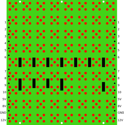
We disassmbled the monster and now we got ~300 LED panels
Each of the 8*9 pixels consists of 5 LEDs = 360 red LEDs per panel
300 panels equals 100.000++ LEDs :)
1 panel full on needs 1.15 AMP @12V
we don't know how to power them yet :)
we are probably going to use the trafo we got out of the old displays.
needs drehstrom outputs 140 AMP 12V weights 40kg+
actually we might use a lot of ATX powersupplies
There is a mailinglist for the blinkofant project see: blinkofant@lists.metalab.at
Pinout
- POUT EQU CENTRO ;the leftmost module will be connected to the POUT-port
- ATTENTION! The bit positions must not be changed!
- 8V, 5V, 12V, GND are not equipped with pins
| pin #
|
function
|
comments
|
| 1
|
data/clock ? comes back out here (Rückleitung Schieberegister)
|
wurscht
|
| 2
|
data/clock ? comes back out here (Rückleitung Schieberegister)
|
wurscht
|
| 3
|
DatLoad EQU 0 ;data bit for loading data and control data
|
wurscht
|
| 4
|
ClkRing EQU 1 ;clock for shift left the whole line
|
CLOCK !!
|
| 5
|
ClkLoad EQU 2 ;clock for shift left & loading all selected modules
|
wurscht
|
| 6
|
ClkBlink EQU 3 ;clock for blinking (0...off, 1...on)
|
clock for blinking of selected rows
|
| 7
|
ClkSteu EQU 4 ;clock for shift left & load control data from DatLoad
|
wurscht
|
| 8
|
DatRing EQU 5 ;data bit for loading data during ClkRing
|
DATA !!
|
| 9
|
Reset EQU 6 ;clear all control data
|
wurscht
|
| 10
|
OnOff EQU 7 ;turn on/off the whole display (0...off, 1...on)
|
turns off ALL the LEDs when pulled to ground
|
When connecting ONE single panel the following pins need to be connected on the output side:
pin 1 -> pin 8
pin 2 -> pin 3
Software
Aktuelle Testfirmware für den Arduino liegt im GIT von 5uper.net ( git clone git@5uper.net:ledmatrix.git )
this is the magic:
SPI.begin();
SPI.setBitOrder(LSBFIRST);
SPI.setDataMode(SPI_MODE0);
SPI.setClockDivider(SPI_CLOCK_DIV128); // biggest divider there is.
...
SPDR = panelData[i];
while(!(SPSR & (1<<SPIF)));
ein panel besteht aus 8*9 pixel (8 spalten mal 9 pixel)
man schiebt 10 bits an daten rein für jede der 8 spalten
9 bits an/aus pro pixel + 1 bit ob diese spalte blinkt
wenn man das blinkybit gesetzt hat kann man auf pin6 eine
clock anlegen die die blinkenrate vorgibt
Borards
- ATTINY2313 .. das wird teuer
- Logic IC für puffer und RX ? welche?
- 2x mod8 buchse (rj45) ?! das wird auch teuer..
- kondensatoren
- eventuell stecker für kabelverbinder zum led modul
|
|


